- Replacement of engine assembly
- Gas leak from exhaust system is repaired
| Last Modified: 07-31-2024 | 6.11:8.1.0 | Doc ID: RM1000000026XRS |
| Model Year Start: 2023 | Model: GR Corolla | Prod Date Range: [09/2022 - 11/2022] |
| Title: EA67F / EA68F (MANUAL TRANSMISSION / TRANSAXLE): MANUAL TRANSAXLE ASSEMBLY: REMOVAL; 2023 MY Corolla Corolla Hatchback GR Corolla [09/2022 - 11/2022] | ||
REMOVAL
CAUTION / NOTICE / HINT
The necessary procedures (adjustment, calibration, initialization or registration) that must be performed after parts are removed and installed, or replaced during manual transaxle assembly removal/installation are shown below.
Necessary Procedures After Parts Removed/Installed/Replaced
|
Replaced Part or Performed Procedure |
Necessary Procedure |
Effect/Inoperative Function when Necessary Procedure not Performed |
Link |
|---|---|---|---|
|
*1: w/ Smart Key System
*2: w/ Steering Lock Function |
|||
|
Replacement of ECM |
Vehicle Identification Number (VIN) registration |
MIL comes on |
|
|
ECU configuration |
- |
||
|
Update ECU security key |
Vehicle Control History (RoB) are stored |
||
|
Heavy Knock History |
- |
||
|
ECU communication ID registration (Immobiliser system) |
Engine start function |
||
|
|
Inspection after repair |
|
|
|
Tire |
ECU Data Initialization (When performing tire replacement after RoB code X2104 is output) |
Active Torque Split AWD System |
|
|
Replacement of ECM*1 |
Code registration (Smart Key System (for Gasoline Model, Start Function)) |
|
|
|
Front wheel alignment adjustment |
|
|
w/ Electric Parking Brake System: w/o Electric Parking Brake System: |
CAUTION:
-
The engine assembly with transaxle is very heavy. Be sure to follow the procedure described in the repair manual, or the engine lifter may suddenly drop or the engine assembly with transaxle may fall off the engine lifter.
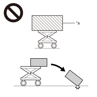
*a
An Object Exceeding Weight Limit of Engine Lifter
-
To prevent burns, do not touch the engine, exhaust manifold or other high temperature components while the engine is hot.
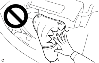
-
The manual transaxle assembly is very heavy. Be sure to follow the procedure described in the repair manual, or the transmission jack may suddenly drop.
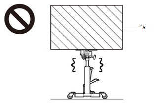
*a
An Object Exceeding Weight Limit of Transmission Jack
NOTICE:
When the manual transaxle assembly is removed, be sure to use a new clutch release cylinder with bearing assembly and new installation bolts. Removal of the manual transaxle assembly allows the compressed clutch release cylinder with bearing assembly to return to its original position. Dust from the moving section may damage the seal of the clutch release cylinder with bearing assembly, possibly causing clutch fluid leaks.
HINT:
When the cable is disconnected / reconnected to the auxiliary battery terminal, systems temporarily stop operating. However, each system has a function that completes learning the first time the system is used.
-
Learning completes when vehicle is driven
Effect/Inoperative Function When Necessary Procedures are not Performed
Necessary Procedures
Link
Front Camera System (for TMC Made)
Drive the vehicle straight ahead at 35 km/h (22 mph) or more for 5 seconds or more.
-
Learning completes when vehicle is operated normally
Effect/Inoperative Function When Necessary Procedures are not Performed
Necessary Procedures
Link
*1: for Hatchback Power Door Lock Control System
- Back door opener*1
Perform door unlock operation with door control switch or electrical key transmitter sub-assembly switch.
PROCEDURE
1. REMOVE ENGINE ASSEMBLY WITH TRANSAXLE
2. REMOVE FLYWHEEL HOUSING SIDE COVER
3. REMOVE STARTER ASSEMBLY
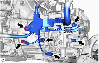
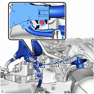
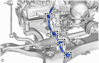
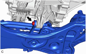
4. DISCONNECT ENGINE WIRE
|
(a) Disconnect the 4 connectors. |
|
(b) Disengage the 2 clamps to disconnect the engine wire from the wire harness clamp bracket.
(c) Remove the 2 bolts and disconnect the engine wire from the manual transaxle assembly.
|
(d) Remove the bolt. |
|
(e) Disengage the 4 clamps to disconnect the engine wire from the wire harness clamp bracket.
|
(f) Disengage the 4 clamps to disconnect the engine wire from the wire harness clamp bracket. |
|
5. REMOVE EXHAUST MANIFOLD CONVERTER SUB-ASSEMBLY
6. REMOVE OUTLET TURBINE ELBOW GASKET
7. REMOVE FRONT SUSPENSION CROSSMEMBER SUB-ASSEMBLY
|
(a) Remove the bolt and front suspension crossmember sub-assembly from the No. 2 engine moving control rod. |
|
8. REMOVE NO. 2 ENGINE MOVING CONTROL ROD
|
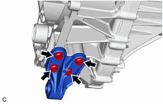
(a) Remove the 4 bolts and No. 2 engine moving control rod from the manual transaxle assembly. |
|
9. REMOVE PROPELLER SHAFT HEAT INSULATOR
|
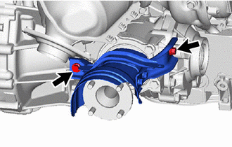
(a) Remove the 2 bolts and propeller shaft heat insulator from the transfer assembly. |
|
10. LOOSEN TRANSFER ASSEMBLY
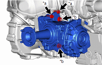
(a) Type A:
|
(1) Loosen the 2 bolts and 2 nuts. |
|
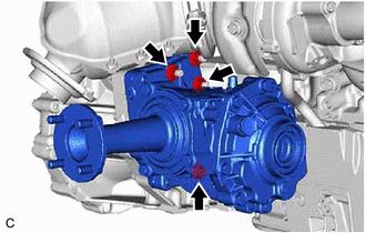
(b) Type B:
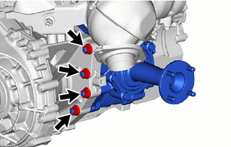
|
(1) Loosen the 4 nuts. |
|
|
(c) Loosen the 4 nuts. |
|
11. REMOVE MANUAL TRANSAXLE ASSEMBLY
|
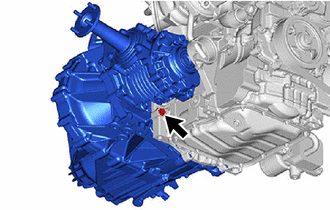
(a) Remove the bolt. |
|
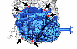
|
(b) Remove the 6 bolts and manual transaxle assembly. |
|
12. REMOVE TRANSFER ASSEMBLY
13. REMOVE BLEEDER TO FLEXIBLE HOSE TUBE
14. REMOVE CLUTCH RELEASE BLEEDER SUB-ASSEMBLY
15. REMOVE CLUTCH RELEASE BEARING PLATE
16. REMOVE CLUTCH RELEASE CYLINDER WITH BEARING ASSEMBLY
17. REMOVE BLEEDER CLUTCH RELEASE TUBE
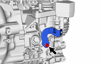
18. REMOVE CLUTCH FLEXIBLE HOSE BRACKET
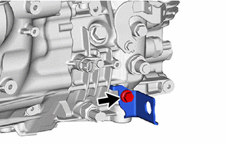
|
(a) Remove the bolt and clutch flexible hose bracket from the manual transaxle assembly. |
|
19. REMOVE EXHAUST PIPE SUPPORT STAY
|
(a) Remove the 2 bolts and exhaust pipe support stay from the manual transaxle assembly. |
|
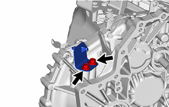
20. REMOVE WIRE HARNESS CLAMP BRACKET
|
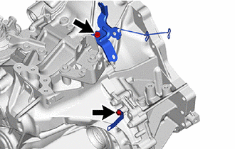
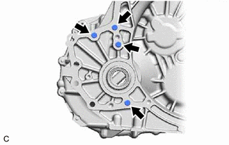
(a) Remove the 2 bolts and 2 wire harness clamp brackets from the manual transaxle assembly. |
|
|
(b) Remove the bolt and wire harness clamp bracket from the manual transaxle assembly. |
|
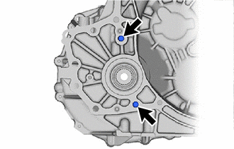
21. REMOVE TRANSFER AND TRANSAXLE SETTING STUD BOLT
(a) Type A:
|
(1) Using 2 nuts, remove the 2 transfer and transaxle setting stud bolts from the manual transaxle assembly. |
|
(b) Type B:
|
(1) Using 2 nuts, remove the 4 transfer and transaxle setting stud bolts from the manual transaxle assembly. |
|
22. REMOVE TRANSMISSION CASE PLUG ASSEMBLY
HINT:
Perform this procedure only when replacement of the transmission case plug assembly or manual transaxle assembly is necessary.
|
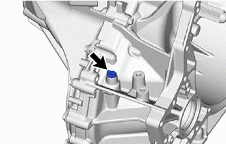
(a) Remove the transmission case plug assembly from the manual transaxle assembly. |
|
|
|
|
![2023 - 2025 MY GR Corolla [09/2022 - ]; G16E-GTS (ENGINE CONTROL): SFI SYSTEM: REGISTRATION](/t3Portal/stylegraphics/info.gif)
