| Last Modified: 07-31-2024 | 6.11:8.1.0 | Doc ID: RM1000000026WFB |
| Model Year Start: 2023 | Model: GR Corolla | Prod Date Range: [09/2022 - 11/2022] |
| Title: PARKING BRAKE: PARKING BRAKE SYSTEM (w/o Electric Parking Brake): ADJUSTMENT; 2023 MY Corolla Corolla Hatchback Corolla HV GR Corolla [09/2022 - 11/2022] | ||
ADJUSTMENT
PROCEDURE
1. INSPECT PARKING BRAKE LEVER TRAVEL
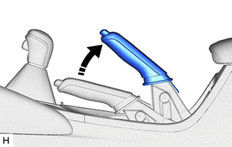
(a) Firmly pull the parking brake lever.
(b) Release the parking brake lever lock and return it to its off position.
|
(c) Slowly pull the parking brake lever to the fully applied position, counting the number of clicks. Parking Brake Lever Travel: 5 to 8 notches at 200 N (20 kgf, 45.0 lbf) If the parking brake lever travel is not as specified, adjust the parking brake lever travel. |
|
2. REMOVE REAR WHEEL (for G16E-GTS)
3. REMOVE DISK WHEEL SPACER (for G16E-GTS)
4. ADJUST PARKING BRAKE SHOE CLEARANCE (for G16E-GTS)
(a) Temporarily install the hub nuts.
HINT:
Secure the rear disc with the hub nuts.
(b) Remove the parking brake shoe adjusting hole plug.
(c) Turn the parking brake shoe adjuster and expand the shoes until the rear disc locks.
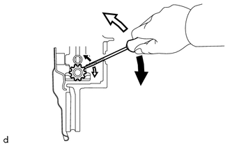

|
Expand |

|
Contract |
(d) Turn and contract the parking brake shoe adjuster until the rear disc can rotate smoothly.
Standard:
Returns 8 notches
(e) Check whether the parking brake drags or not.
(f) Install the parking brake shoe adjusting hole plug.
(g) Remove the hub nuts.
5. ADJUST PARKING BRAKE LEVER TRAVEL (except G16E-GTS)
|
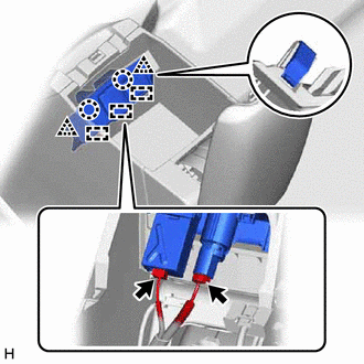
(a) Disengage the 2 claws, 2 clips and 3 guides to separate the No. 1 box panel. |
|
(b) Disconnect the 2 connectors and remove the No. 1 box panel.
(c) Release the parking brake lever lock and return it to its off position.
|
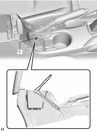
(d) Loosen the No. 1 wire adjusting nut to completely release the parking brake cable as shown in the illustration. NOTICE: Do not remove the No. 1 wire adjusting nut. |
|
(e) Start the engine and depress the brake pedal several times.
(f) Turn the ignition switch off.
(g) Turn the No. 1 wire adjusting nut until the parking brake lever travel is corrected to be within the specified range.
Parking Brake Lever Travel:
5 to 8 notches at 200 N (20 kgf, 45.0 lbf)
(h) Operate the parking brake lever 3 to 4 times, and check the parking brake lever travel.
(i) Check that the parking brake does not drag.
(j) Connect the 2 connectors.
(k) Engage the 3 guides, 2 clips and 2 claws to install the No. 1 box panel.
6. INSPECT REAR DISC BRAKE CYLINDER OPERATION LEVER AND STOPPER CLEARANCE (except G16E-GTS)
|
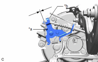
(a) Release the parking brake lever and check that the clearance between the rear disc brake cylinder operation lever and the stopper is as specified below. Clearance: 0.5 mm (0.0197 in.) or less If the clearance is not as specified, replace the rear disc brake cylinder assembly. |
|
7. ADJUST PARKING BRAKE LEVER TRAVEL (for G16E-GTS)
(a) Remove the parking brake hole cover sub-assembly.
(b) Release the parking brake lever lock and return it to its off position.
|
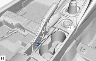
(c) Loosen the No. 1 wire adjusting nut to completely release the parking brake cable as shown in the illustration. Parking Brake Lever Travel: 5 to 8 notches at 200 N (20 kgf, 45.0 lbf) NOTICE: Do not remove the No. 1 wire adjusting nut. |
|
(d) Operate the parking brake lever 3 to 4 times, and check the parking brake lever travel.
(e) Check that the parking brake does not drag.
(f) Install the parking brake hole cover sub-assembly.
8. INSTALL DISK WHEEL SPACER (for G16E-GTS)
9. INSTALL REAR WHEEL (for G16E-GTS)
10. INSPECT BRAKE WARNING LIGHT
(a) When operating the parking brake lever, check that the brake warning light illuminates.
Standard:
The brake warning light always illuminates at the first click.
|
|
|
![2023 - 2025 MY Corolla Corolla Hatchback Corolla HV GR Corolla [09/2022 - ]; MAINTENANCE: TIRE AND WHEEL: REMOVAL](/t3Portal/stylegraphics/info.gif)
