| Last Modified: 05-13-2024 | 6.11:8.1.0 | Doc ID: RM1000000026PYC |
| Model Year Start: 2023 | Model: Corolla HV | Prod Date Range: [09/2022 - ] |
| Title: HYBRID / BATTERY CONTROL: MOTOR GENERATOR CONTROL SYSTEM (for LITHIUM-ION BATTERY with PA10): P0A1B94; Drive Motor "A" Control Module Unexpected Operation; 2023 - 2025 MY Corolla HV [09/2022 - ] | ||
|
DTC |
P0A1B94 |
Drive Motor "A" Control Module Unexpected Operation |
DTC SUMMARY
MALFUNCTION DESCRIPTION
For the calculation processing (in particular, calculation processing related to driving force such as torque calculations and inverter control) that takes place inside the motor generator control ECU (MG ECU), the microcomputers built into the motor generator control ECU (MG ECU) monitor each other and check each other's calculations for appropriateness.
The cause of this malfunction may be the following:
Motor generator control ECU internal malfunction
- Motor generator control ECU (MG ECU) malfunction
DESCRIPTION
When the separate microcomputers within the motor generator control ECU (MG ECU) that monitor each other detect an abnormality in the information, a DTC is stored.
|
DTC No. |
Detection Item |
DTC Detection Condition |
Trouble Area |
MIL |
Warning Indicate |
Note |
|---|---|---|---|---|---|---|
|
P0A1B94 |
Drive Motor "A" Control Module Unexpected Operation |
When the separate microcomputers within the motor generator control ECU (MG ECU) that monitor each other detect a value in the information that differs from what is expected for a specified period of time. (1 trip detection logic) |
|
Comes on |
Master Warning: Comes on |
SAE Code: P0A1B |
MONITOR DESCRIPTION
The motor generator control ECU (MG ECU) monitors the microcomputers within the motor generator control ECU (MG ECU). If the internal operation is malfunctioning, the motor generator control ECU (MG ECU) illuminates the MIL and stores a DTC.
MONITOR STRATEGY
|
Related DTCs |
P0A1B (INF P0A1B94): Drive motor "A" control module |
|
Required sensors/components |
Inverter with converter assembly (MG ECU) |
|
Frequency of operation |
Continuous |
|
Duration |
TMC's intellectual property |
|
MIL operation |
1 driving cycle |
|
Sequence of operation |
None |
TYPICAL ENABLING CONDITIONS
|
The monitor will run whenever the following DTCs are not stored |
TMC's intellectual property |
|
Other conditions belong to TMC's intellectual property |
- |
TYPICAL MALFUNCTION THRESHOLDS
|
TMC's intellectual property |
- |
COMPONENT OPERATING RANGE
|
Motor generator control ECU |
DTC P0A1B (INF P0A1B94) is not detected |
CONFIRMATION DRIVING PATTERN
HINT:
-
After repair has been completed, clear the DTC and then check that the vehicle has returned to normal by performing the following All Readiness check procedure.
Click here
![2023 - 2025 MY Corolla HV [09/2022 - ]; HYBRID / BATTERY CONTROL: MOTOR GENERATOR CONTROL SYSTEM (for LITHIUM-ION BATTERY with PA10): UTILITY](/t3Portal/stylegraphics/info.gif)
-
When clearing the permanent DTCs, refer to the "CLEAR PERMANENT DTC" procedure.
Click here
- Connect the GTS to the DLC3.
- Turn the ignition switch to ON and turn the GTS on.
- Clear the DTCs (even if no DTCs are stored, perform the clear DTC procedure).
- Turn the ignition switch off and wait for 2 minutes or more.
- Turn the ignition switch to ON and turn the GTS on.
-
With ignition switch ON and wait for 2 minutes or more. [*1]
HINT:
- If the vehicle has returned to normal, it can be driven after turning the ignition switch to ON (READY).
-
[*1]: Normal judgment procedure.
The normal judgment procedure is used to complete DTC judgment and also used when clearing permanent DTCs.
- Enter the following menus: Powertrain / Motor Generator / Utility / All Readiness.
-
Check the DTC judgment result.
HINT:
- If the judgment result shows NORMAL, the system is normal.
- If the judgment result shows ABNORMAL, the system has a malfunction.
- If the judgment result shows INCOMPLETE, perform the normal judgment procedure again.
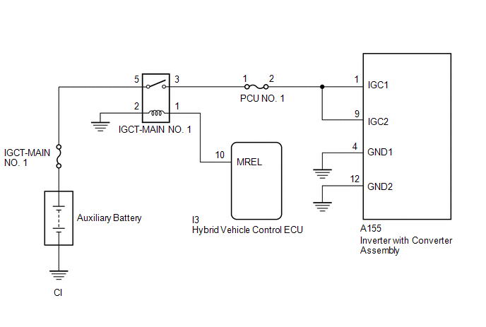
WIRING DIAGRAM
CAUTION / NOTICE / HINT
NOTICE:
-
After the ignition switch is turned off, there may be a waiting time before disconnecting the negative (-) auxiliary battery terminal.
Click here
-
When disconnecting and reconnecting the auxiliary battery
HINT:
When disconnecting and reconnecting the auxiliary battery, there is an automatic learning function that completes learning when the respective system is used.
Click here
PROCEDURE
|
1. |
CHECK AUXILIARY BATTERY TERMINAL (CONTACT PROBLEM) |
(a) Check the connection of the negative (-) and positive (+) auxiliary battery terminals.
OK:
The terminals are connected securely and there is no contact problem.
HINT:
If performing a simulation test, turn the ignition switch to ON and shake the wire harnesses vertically and horizontally before checking for DTCs.
| NG |

|
|

|
2. |
CHECK GROUND WIRE CONNECTION CONDITION |
(a) Check the installation condition of the ground wires CI.
OK:
The ground wires CI are securely installed.
HINT:
If performing a simulation test, turn the ignition switch to ON and shake the wire harnesses vertically and horizontally before checking for DTCs.
| NG |
|
|
|
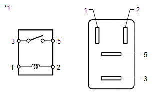
3. |
CHECK RELAY (IGCT-MAIN NO. 1) |
(a) Check the IGCT-MAIN NO. 1 relay for improper installation.
OK:
The relay is installed securely.
HINT:
If performing a simulation test, turn the ignition switch to ON and gently vibrate the IGCT-MAIN NO. 1 relay with a finger before checking for DTCs.
(b) Remove the IGCT-MAIN NO. 1 relay from the No. 1 engine room relay block and No. 1 junction block assembly.
|
(c) Measure the resistance according to the value(s) in the table below. Standard Resistance:
|
|
(d) Install the IGCT-MAIN NO. 1 relay.
| NG |
|
|
|
4. |
CHECK DTC OUTPUT (MOTOR GENERATOR) |
(a) Check for DTCs.
HINT:
Check the DTCs that were output when the vehicle was brought to the workshop.
Powertrain > Motor Generator > Trouble Codes
|
Result |
Proceed to |
|---|---|
|
P0A1B94 only is output. |
A |
|
DTCs except P0A1B94 are output. |
B |
(b) Turn the ignition switch off.
| A |
|
| B |
|
GO TO DTC CHART (HYBRID CONTROL SYSTEM) |
|
5. |
CONNECT SECURELY |
| NEXT |
|
|
6. |
CONNECT SECURELY |
| NEXT |
|
|
7. |
REPAIR OR REPLACE MALFUNCTIONING PARTS |
|
|
8. |
CLEAR DTC |
(a) Read and record the DTCs and Freeze Frame Data.
Powertrain > Motor Generator > Trouble Codes
(b) Clear the DTCs and Freeze Frame Data.
Powertrain > Motor Generator > Clear DTCs
(c) Turn the ignition switch off and wait for 2 minutes or more.
|
|
9. |
SIMULATION TEST |
(a) Turn the ignition switch to ON and wait for 2 minutes or more.
(b) Turn the ignition switch off.
|
|
10. |
CHECK DTC OUTPUT (MOTOR GENERATOR) |
(a) Check for DTCs.
Powertrain > Motor Generator > Trouble Codes
|
Result |
Proceed to |
|---|---|
|
No DTCs are output. |
A |
|
P0A1B94 only is output. |
B |
|
DTCs except P0A1B94 are output. |
C |
(b) Turn the ignition switch off.
| A |
|
END |
| B |
|
| C |
|
GO TO DTC CHART (MOTOR GENERATOR CONTROL SYSTEM) |
|
|
|