| Last Modified: 05-13-2024 | 6.11:8.1.0 | Doc ID: RM1000000026PVV |
| Model Year Start: 2023 | Model: Corolla HV | Prod Date Range: [09/2022 - ] |
| Title: HYBRID / BATTERY CONTROL: HYBRID CONTROL SYSTEM (for LITHIUM-ION BATTERY with PA10): U011187; Lost Communication with Hybrid/EV Battery Energy Control Module "A" Missing Message; 2023 - 2025 MY Corolla HV [09/2022 - ] | ||
|
DTC |
U011187 |
Lost Communication with Hybrid/EV Battery Energy Control Module "A" Missing Message |
DESCRIPTION
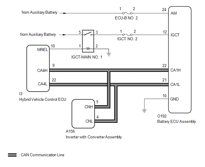
The hybrid vehicle control ECU transmits and receives signals via CAN communication to and from the battery ECU assembly.
|
DTC No. |
Detection Item |
DTC Detection Condition |
Trouble Area |
MIL |
Warning Indicate |
Note |
|---|---|---|---|---|---|---|
|
U011187 |
Lost Communication with Hybrid/EV Battery Energy Control Module "A" Missing Message |
The hybrid vehicle control ECU cannot receive signals from the battery ECU assembly (1 trip detection logic) |
|
Comes on |
Master Warning: Comes on |
SAE Code: U0111 |
MONITOR DESCRIPTION
If the hybrid vehicle control ECU detects a problem with CAN communication with the ECU, it will illuminate the MIL and store a DTC.
MONITOR STRATEGY
|
Related DTCs |
U0111 (INF U011187): Lost communication with BECM (Battery bus) verify communication |
|
Required sensors/components |
Main: Battery ECU assembly Sub: Hybrid vehicle control ECU |
|
Frequency of operation |
Continuous |
|
Duration |
TMC's intellectual property |
|
MIL operation |
Immediately |
|
Sequence of operation |
None |
TYPICAL ENABLING CONDITIONS
|
The monitor will run whenever the following DTCs are not stored |
TMC's intellectual property |
|
Other conditions belong to TMC's intellectual property |
- |
TYPICAL MALFUNCTION THRESHOLDS
|
TMC's intellectual property |
- |
COMPONENT OPERATING RANGE
|
Hybrid vehicle control ECU |
DTC U0111 (INF U011187) is not detected |
CONFIRMATION DRIVING PATTERN
HINT:
-
After repair has been completed, clear the DTC and then check that the vehicle has returned to normal by performing the following All Readiness check procedure.
Click here
![2023 - 2025 MY Corolla HV [09/2022 - ]; HYBRID / BATTERY CONTROL: HYBRID CONTROL SYSTEM (for LITHIUM-ION BATTERY with PA10): UTILITY](/t3Portal/stylegraphics/info.gif)
-
When clearing the permanent DTCs, refer to the "CLEAR PERMANENT DTC" procedure.
Click here
- Connect the GTS to the DLC3.
- Turn the ignition switch to ON and turn the GTS on.
- Clear the DTCs (even if no DTCs are stored, perform the clear DTC procedure).
- Turn the ignition switch off and wait for 2 minutes or more.
- Turn the ignition switch to ON and turn the GTS on.
-
Turn the ignition switch to ON (READY) and wait for 2 minutes or more. [*1]
HINT:
[*1] : Normal judgment procedure.
The normal judgment procedure is used to complete DTC judgment and also used when clearing permanent DTCs.
- Enter the following menus: Powertrain / Hybrid Control / Utility / All Readiness.
-
Check the DTC judgment result.
HINT:
- If the judgment result shows NORMAL, the system is normal.
- If the judgment result shows ABNORMAL, the system has a malfunction.
- If the judgment result shows INCOMPLETE, perform the normal judgment procedure again.
WIRING DIAGRAM
CAUTION / NOTICE / HINT
CAUTION:
Refer to the precautions before inspecting high voltage circuit.
Click here
NOTICE:
-
After the ignition switch is turned off, there may be a waiting time before disconnecting the negative (-) auxiliary battery terminal.
Click here
-
When disconnecting and reconnecting the auxiliary battery
HINT:
When disconnecting and reconnecting the auxiliary battery, there is an automatic learning function that completes learning when the respective system is used.
Click here
PROCEDURE
|
1. |
CHECK DTC OUTPUT (HV BATTERY) |
(a) Check and record any HV Battery DTCs and freeze frame data. Check for DTCs.
Powertrain > HV Battery > Trouble Codes
|
Result |
Proceed to |
|---|---|
|
DTCs related to Hybrid Battery System are not output. |
A |
|
DTCs related to Hybrid Battery System are output. |
B |
(b) Turn the ignition switch off.
| B |

|
|

|
2. |
CHECK BATTERY ECU ASSEMBLY (IGCT VOLTAGE) |
CAUTION:
Be sure to wear insulated gloves.
(a) Check that the service plug grip is not installed.
NOTICE:
After removing the service plug grip, do not turn the ignition switch to ON (READY), unless instructed by the repair manual because this may cause a malfunction.
|
(b) Disconnect the battery ECU assembly connector. NOTICE:
|
|

(c) Measure the voltage according to the value(s) in the table below.
Standard Voltage:
|
Tester Connection |
Condition |
Specified Condition |
|---|---|---|
|
O192-24 (AM) - O192-10 (GND) |
Ignition switch off |
11 to 14 V |
(d) Connect the cable to the negative (-) auxiliary battery terminal.
(e) Turn the ignition switch to ON.
(f) Measure the voltage according to the value(s) in the table below.
Standard Voltage:
|
Tester Connection |
Condition |
Specified Condition |
|---|---|---|
|
O192-12 (IGCT) - O192-10 (GND) |
Ignition switch ON |
11 to 14 V |
NOTICE:
- Turning the ignition switch to ON with the service plug grip removed causes other DTCs to be stored. Clear the DTCs after performing this inspection.
- If the ignition switch is turned to ON with the connectors disconnected, other DTCs will be stored. Be sure to clear the DTCs after the inspection.
HINT:
As there might be an intermittent malfunction in the battery ECU assembly power source circuit, inspect the following even if the measured voltage is as specified:
- Installation condition of fuse(s) (before removing fuse(s)) (IGCT circuit)
- Fuse condition (before and after removing fuse(s)) (IGCT circuit)
- Connection condition of connectors (IGCT circuit)
- Wire harness condition (IGCT circuit)
- Wire harness condition (GND circuit)
(g) Turn the ignition switch off.
(h) Disconnect the cable from the negative (-) auxiliary battery terminal.
(i) Reconnect the battery ECU assembly connector.
| NG |
|
REPAIR OR REPLACE HARNESS OR CONNECTOR (BATTERY ECU ASSEMBLY POWER SOURCE CIRCUIT) |
|
|
3. |
CHECK HARNESS AND CONNECTOR (HYBRID VEHICLE CONTROL ECU - BATTERY ECU ASSEMBLY) |
CAUTION:
Be sure to wear insulated gloves.
(a) Check that the service plug grip is not installed.
NOTICE:
After removing the service plug grip, do not turn the ignition switch to ON (READY), unless instructed by the repair manual because this may cause a malfunction.
(b) Disconnect the hybrid vehicle control ECU connector.
NOTICE:
- Before disconnecting the connector, check that it is not loose or disconnected.
- Check that each connector between the hybrid vehicle control ECU and battery ECU assembly is not loose or disconnected.
|
(c) Disconnect the battery ECU assembly connector. NOTICE:
|
|
(d) Disconnect the inverter with converter assembly connector.
NOTICE:
- Before disconnecting the connector, check that it is not loose or disconnected.
- Check the terminals of the connector for deformation and corrosion.
(e) Measure the resistance according to the value(s) in the table below.
Standard Resistance:
|
Tester Connection |
Condition |
Specified Condition |
|---|---|---|
|
O192-22 (CA1H) - I3-9 (CA4H) |
Ignition switch off |
Below 1 Ω |
|
O192-21 (CA1L) - I3-22 (CA4L) |
Ignition switch off |
Below 1 Ω |
|
I3-9 (CA4H) - Other terminals and body ground |
Ignition switch off |
10 kΩ or higher |
|
I3-22 (CA4L) - Other terminals and body ground |
Ignition switch off |
10 kΩ or higher |
NOTICE:
Make sure that each connector between the battery ECU assembly and hybrid vehicle control ECU is not loose or disconnected and its terminals are not deformed or corroded.
(f) Connect the cable to the negative (-) auxiliary battery terminal.
(g) Turn the ignition switch to ON.
(h) Measure the voltage according to the value(s) in the table below.
Standard Voltage:
|
Tester Connection |
Condition |
Specified Condition |
|---|---|---|
|
O192-22 (CA1H) - Body ground |
Ignition switch ON |
Below 1 V |
|
O192-21 (CA1L) - Body ground |
Ignition switch ON |
Below 1 V |
NOTICE:
- Turning the ignition switch to ON with the service plug grip removed causes other DTCs to be stored. Clear the DTCs after performing this inspection.
- If the ignition switch is turned to ON with the connectors disconnected, other DTCs will be stored. Be sure to clear the DTCs after the inspection.
(i) Turn the ignition switch off.
(j) Disconnect the cable from the negative (-) auxiliary battery terminal.
(k) Reconnect the inverter with converter assembly connector.
(l) Reconnect the battery ECU assembly connector.
(m) Reconnect the hybrid vehicle control ECU connector.
| NG |
|
REPAIR OR REPLACE HARNESS OR CONNECTOR |
|
|
4. |
CHECK HYBRID VEHICLE CONTROL ECU |
CAUTION:
Be sure to wear insulated gloves.
(a) Check that the service plug grip is not installed.
NOTICE:
After removing the service plug grip, do not turn the ignition switch to ON (READY), unless instructed by the repair manual because this may cause a malfunction.
|
(b) Disconnect the battery ECU assembly connector. NOTICE:
|
|
(c) Connect the cable to the negative (-) auxiliary battery terminal.
(d) Turn the ignition switch to ON.
(e) Measure the voltage according to the value(s) in the table below.
Standard Voltage:
|
Tester Connection |
Condition |
Specified Condition |
|---|---|---|
|
O192-22 (CA1H) - O192-10 (GND) |
Ignition switch ON |
2.5 to 3.5 V |
|
O192-21 (CA1L) - O192-10 (GND) |
Ignition switch ON |
1.5 to 2.5 V |
NOTICE:
- Turning the ignition switch to ON with the service plug grip removed causes other DTCs to be stored. Clear the DTCs after performing this inspection.
- If the ignition switch is turned to ON with the connectors disconnected, other DTCs will be stored. Be sure to clear the DTCs after the inspection.
(f) Turn the ignition switch off.
(g) Disconnect the cable from the negative (-) auxiliary battery terminal.
(h) Measure the resistance according to the value(s) in the table below.
Standard Resistance:
|
Tester Connection |
Condition |
Specified Condition |
|---|---|---|
|
O192-22 (CA1H) - O192-21 (CA1L) |
Ignition switch off |
108 to 132 Ω |
(i) Reconnect the battery ECU assembly connector.
| OK |
|
| NG |
|
|
|
|