| Last Modified: 05-13-2024 | 6.11:8.1.0 | Doc ID: RM1000000026LJA |
| Model Year Start: 2023 | Model: GR Corolla | Prod Date Range: [09/2022 - ] |
| Title: AUDIO / VIDEO: AUDIO AND VISUAL SYSTEM (for Single Knob Type): U11D087; Lost Local Communication with MET Missing Message; 2023 - 2025 MY Corolla Corolla Hatchback Corolla HV GR Corolla [09/2022 - ] | ||
|
DTC |
U11D087 |
Lost Local Communication with MET Missing Message |
DESCRIPTION
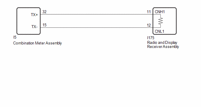
These DTCs are stored when the radio and display receiver assembly detects a communication malfunction with the combination meter assembly.
|
DTC No. |
Detection Item |
DTC Detection Condition |
Trouble Area |
DTC Output from |
Priority |
|---|---|---|---|---|---|
|
U11D087 |
Lost Local Communication with MET Missing Message |
Communication malfunction between radio and display receiver assembly and combination meter assembly for 30 seconds or more (2 trip detection logic) |
|
Navigation System |
A |
WIRING DIAGRAM

CAUTION / NOTICE / HINT
NOTICE:
- Depending on the parts that are replaced during vehicle inspection or maintenance, performing initialization, registration or calibration may be needed.
- Inspect the fuses for circuits related to this system before performing the following procedure.
- When replacing the combination meter assembly, make sure to replace it with a new one. If a combination meter assembly which was installed to another vehicle is used, the information stored in the combination meter assembly will not match the information from the vehicle and a DTC may be stored.
- Before measuring the resistance of the CAN bus, turn the ignition switch off and leave the vehicle for 1 minute or more without operating the key, switches or opening or closing the doors. After that, disconnect the cable from the negative (-) battery terminal and leave the vehicle for 1 minute or more before measuring the resistance.
- After turning the ignition switch off, waiting time may be required before disconnecting the cable from the negative (-) battery terminal. Therefore make sure to read the disconnecting the cable from the negative (-) battery terminal notices before proceeding with work.
HINT:
- Before disconnecting related connectors for inspection, push in on the connector body to check that each connector is not loose or disconnected.
- When a connector is disconnected, check that the terminals and connector body are not cracked, deformed or corroded.
- When the cable is disconnected / reconnected to the battery terminal, systems temporarily stop operating. However, each system has a function that completes learning the first time the system is used.
PROCEDURE
|
1. |
CHECK FOR CAN BUS WIRE (COMBINATION METER ASSEMBLY MAIN WIRE) |
Pre-procedure1
(a) Disconnect the cable from the negative (-) battery terminal.
(b) Disconnect the I5 combination meter assembly connector.
Procedure1
(c) Measure the resistance according to the value(s) in the table below.
Standard Resistance:
|
Tester Connection |
Condition |
Specified Condition |
|---|---|---|
|
I5-32 (TX+) - I5-15 (TX-) |
Cable disconnected from negative (-) battery terminal |
108 to 132 Ω |
|
I5-32 (TX+) - I26-4 (CG) |
Cable disconnected from negative (-) battery terminal |
200 Ω or higher |
|
I5-15 (TX-) - I26-4 (CG) |
Cable disconnected from negative (-) battery terminal |
200 Ω or higher |
|
I5-32 (TX+) - I26-16 (BAT) |
Cable disconnected from negative (-) battery terminal |
6 kΩ or higher |
|
I5-15 (TX-) - I26-16 (BAT) |
Cable disconnected from negative (-) battery terminal |
6 kΩ or higher |
Post-procedure1
(d) None
| OK |

|
|
|
2. |
CHECK FOR CAN BUS WIRE (RADIO AND DISPLAY RECEIVER ASSEMBLY MAIN WIRE) |
Pre-procedure1
(a) Disconnect the cable from the negative (-) battery terminal.
(b) Disconnect the I175 radio and display receiver assembly connector.
Procedure1
(c) Measure the resistance according to the value(s) in the table below.
Standard Resistance:
|
Tester Connection |
Condition |
Specified Condition |
|---|---|---|
|
I175-11 (CNH1) - I175-12 (CNL1) |
Cable disconnected from negative (-) battery terminal |
108 to 132 Ω |
|
I175-11 (CNH1) - I26-4 (CG) |
Cable disconnected from negative (-) battery terminal |
200 Ω or higher |
|
I175-12 (CNL1) - I26-4 (CG) |
Cable disconnected from negative (-) battery terminal |
200 Ω or higher |
|
I175-11 (CNH1) - I26-16 (BAT) |
Cable disconnected from negative (-) battery terminal |
6 kΩ or higher |
|
I175-12 (CNL1) - I26-16 (BAT) |
Cable disconnected from negative (-) battery terminal |
6 kΩ or higher |
Post-procedure1
(d) None
| OK |

|
| NG |

|
REPAIR OR REPLACE HARNESS OR CONNECTOR |
|
|
|
![2023 - 2025 MY Corolla Corolla Hatchback Corolla HV GR Corolla [09/2022 - ]; AUDIO / VIDEO: AUDIO AND VISUAL SYSTEM (for Single Knob Type): PRECAUTION](/t3Portal/stylegraphics/info.gif)
