| Last Modified: 01-27-2025 | 6.11:8.1.0 | Doc ID: RM1000000026LIT |
| Model Year Start: 2023 | Model: GR Corolla | Prod Date Range: [09/2022 - 11/2022] |
| Title: AUDIO / VIDEO: AUDIO AND VISUAL SYSTEM (for 8 Inch Display Type (w/ Single Knob Type) or 10.5 Inch Display Type): B15C371; Speaker Output Short Actuator Stuck; 2023 MY Corolla Corolla Hatchback Corolla HV GR Corolla [09/2022 - 11/2022] | ||
|
DTC |
B15C371 |
Speaker Output Short Actuator Stuck |
DESCRIPTION
This DTC is stored when the stereo component amplifier assembly*1 or radio and display receiver assembly*2 detects a short in a speaker circuit.
|
DTC No. |
Detection Item |
DTC Detection Condition |
Trouble Area |
DTC Output from |
Priority |
|---|---|---|---|---|---|
|
B15C371 |
Speaker Output Short Actuator Stuck |
When any of the following conditions is met: (2 trip detection logic)
|
|
Navigation System |
A |
- *1: w/ "JBL" Sound System
- *2: w/o "JBL" Sound System
WIRING DIAGRAM
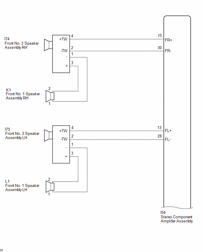
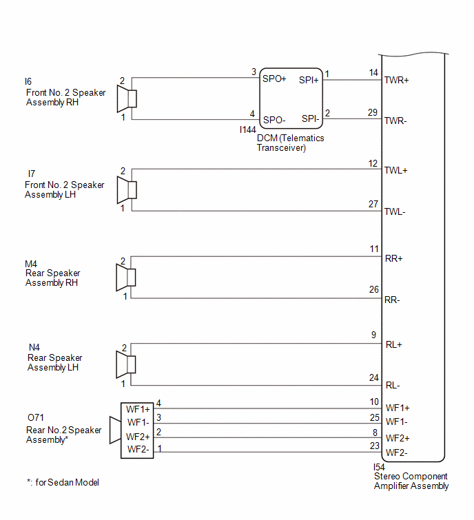
w/ "JBL" Sound System
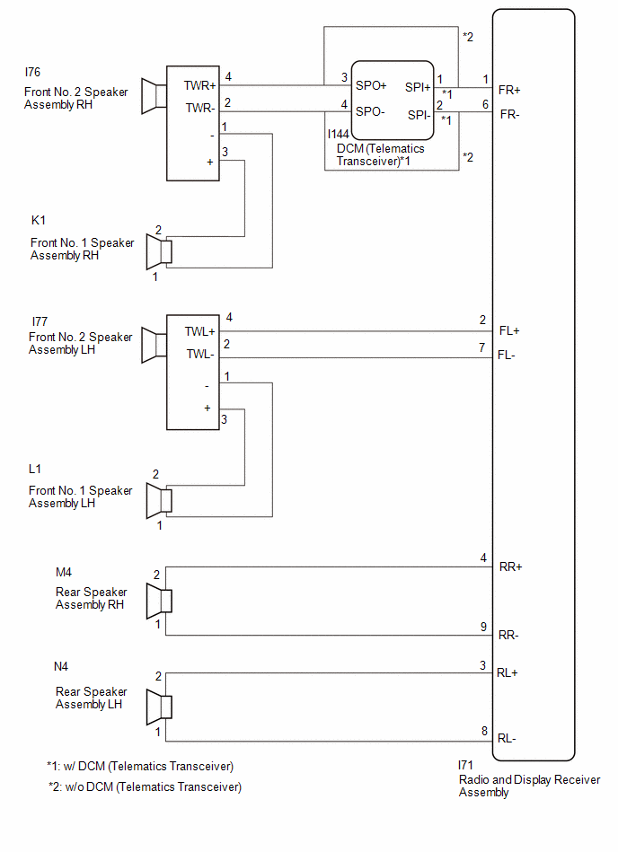
w/o "JBL" Sound System
CAUTION / NOTICE / HINT
NOTICE:
Depending on the parts that are replaced during vehicle inspection or maintenance, performing initialization, registration or calibration may be needed.
Click here
![2023 - 2025 MY Corolla Corolla Hatchback Corolla HV GR Corolla [09/2022 - ]; AUDIO / VIDEO: AUDIO AND VISUAL SYSTEM (for 8 Inch Display Type (w/ Single Knob Type) or 10.5 Inch Display Type): PRECAUTION](/t3Portal/stylegraphics/info.gif)
PROCEDURE
|
1. |
CHECK MODEL |
(a) Choose the model to be inspected.
|
Result |
Proceed to |
|---|---|
|
w/o "JBL" Sound System with Telematics Transceiver |
A |
|
w/o "JBL" Sound System without Telematics Transceiver |
B |
|
w/ "JBL" Sound System with Telematics Transceiver |
C |
| B |

|
| C |
|
|

|
2. |
CHECK HARNESS AND CONNECTOR (RADIO AND DISPLAY RECEIVER ASSEMBLY - EACH SPEAKER OR DCM (TELEMATICS TRANSCEIVER)) |
(a) Disconnect the I71 radio and display receiver assembly connector.
(b) Disconnect the I144 DCM (telematics transceiver) connector.
(c) Disconnect the I77 front No. 2 speaker assembly LH connector.
(d) Disconnect the N4 and M4 rear speaker assembly connectors.
(e) Measure the resistance according to the value(s) in the table below.
Standard Resistance:
|
Tester Connection |
Condition |
Specified Condition |
|---|---|---|
|
I71-1 (FR+) or I144-1 (SPI+) - Body ground |
Always |
10 kΩ or higher |
|
I71-6 (FR-) or I144-2 (SPI-) - Body ground |
Always |
10 kΩ or higher |
|
I71-2 (FL+) or I77-4 (TWL+) - Body ground |
Always |
10 kΩ or higher |
|
I71-7 (FL-) or I77-2 (TWL-) - Body ground |
Always |
10 kΩ or higher |
|
I71-4 (RR+) or M4-2 - Body ground |
Always |
10 kΩ or higher |
|
I71-9 (RR-) or M4-1 - Body ground |
Always |
10 kΩ or higher |
|
I71-3 (RL+) or N4-2 - Body ground |
Always |
10 kΩ or higher |
|
I71-8 (RL-) or N4-1 - Body ground |
Always |
10 kΩ or higher |
| NG |
|
REPAIR OR REPLACE HARNESS OR CONNECTOR |
|
|
3. |
CHECK HARNESS AND CONNECTOR (DCM (TELEMATICS TRANSCEIVER) - FRONT NO. 2 SPEAKER ASSEMBLY RH) |
(a) Disconnect the I144 DCM (telematics transceiver) connector.
(b) Disconnect the I76 front No. 2 speaker assembly RH connector.
(c) Measure the resistance according to the value(s) in the table below.
Standard Resistance:
|
Tester Connection |
Condition |
Specified Condition |
|---|---|---|
|
I144-3 (SPO+) or I76-4 (TWR+) - Body ground |
Always |
10 kΩ or higher |
|
I144-4 (SPO-) or I76-2 (TWR-) - Body ground |
Always |
10 kΩ or higher |
| NG |
|
REPAIR OR REPLACE HARNESS OR CONNECTOR |
|
|
4. |
CHECK HARNESS AND CONNECTOR (FRONT NO. 1 SPEAKER ASSEMBLY - FRONT NO. 2 SPEAKER ASSEMBLY) |
(a) Disconnect the K1 and L1 front No. 1 speaker assembly connectors.
(b) Disconnect the I76 and I77 front No. 2 speaker assembly connectors.
(c) Measure the resistance according to the value(s) in the table below.
Standard Resistance:
|
Tester Connection |
Condition |
Specified Condition |
|---|---|---|
|
L1-2 or I77-3 (+) - Body ground |
Always |
10 kΩ or higher |
|
L1-1 or I77-1 (-) - Body ground |
Always |
10 kΩ or higher |
|
K1-2 or I76-3 (+) - Body ground |
Always |
10 kΩ or higher |
|
K1-1 or I76-1 (-) - Body ground |
Always |
10 kΩ or higher |
| NG |
|
REPAIR OR REPLACE HARNESS AND CONNECTOR |
|
|
5. |
INSPECT FRONT NO. 1 SPEAKER ASSEMBLY |
Click here
| NG |
|
|
|
6. |
INSPECT REAR SPEAKER ASSEMBLY |
Click here
| NG |
|
|
|
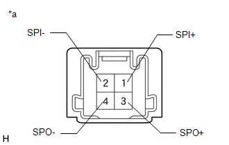
7. |
INSPECT TELEMATICS TRANSCEIVER |
|
(a) Disconnect the telematics transceiver connector. |
|
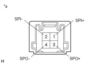
(b) Measure the resistance according to the value(s) in the table below.
Standard Resistance:
|
Tester Connection |
Condition |
Specified Condition |
|---|---|---|
|
1 (SPI+) - 3 (SPO+) |
Always |
Below 1 Ω |
|
2 (SPI-) - 4 (SPO-) |
Always |
Below 1 Ω |
|
1 (SPI+) - 2 (SPI-) |
Always |
10 kΩ or higher |
|
3 (SPO+) - 4 (SPO-) |
Always |
10 kΩ or higher |
| NG |
|
|
|
8. |
REPLACE FRONT NO.2 SPEAKER ASSEMBLY |
(a) Replace the speaker assembly with a new or known good one.
Click here
|
|
9. |
CHECK FOR DTC |
(a) Clear the DTCs.
Body Electrical > Navigation System > Clear DTCs
(b) Turn the ignition switch off.
(c) Check for DTCs and proceed to the following step.
Body Electrical > Navigation System > Trouble Codes
|
Result |
Proceed to |
|---|---|
|
DTCs are not output |
A |
|
DTC B15C371 is output |
B |
| A |
|
END |
| B |
|
|
10. |
CHECK HARNESS AND CONNECTOR (RADIO AND DISPLAY RECEIVER ASSEMBLY - EACH SPEAKER) |
(a) Disconnect the I71 radio and display receiver assembly connector.
(b) Disconnect the I76 and I77 front No. 2 speaker assembly connectors.
(c) Disconnect the N4 and M4 rear speaker assembly connectors.
(d) Measure the resistance according to the value(s) in the table below.
Standard Resistance:
|
Tester Connection |
Condition |
Specified Condition |
|---|---|---|
|
I71-1 (FR+) or I76-4 (TWR+) - Body ground |
Always |
10 kΩ or higher |
|
I71-6 (FR-) or I76-2 (TWR-) - Body ground |
Always |
10 kΩ or higher |
|
I71-2 (FL+) or I77-4 (TWL+) - Body ground |
Always |
10 kΩ or higher |
|
I71-7 (FL-) or I77-2 (TWL-) - Body ground |
Always |
10 kΩ or higher |
|
I71-4 (RR+) or M4-2 - Body ground |
Always |
10 kΩ or higher |
|
I71-9 (RR-) or M4-1 - Body ground |
Always |
10 kΩ or higher |
|
I71-3 (RL+) or N4-2 - Body ground |
Always |
10 kΩ or higher |
|
I71-8 (RL-) or N4-1 - Body ground |
Always |
10 kΩ or higher |
| NG |
|
REPAIR OR REPLACE HARNESS OR CONNECTOR |
|
|
11. |
CHECK HARNESS AND CONNECTOR (FRONT NO. 1 SPEAKER ASSEMBLY - FRONT NO. 2 SPEAKER ASSEMBLY) |
(a) Disconnect the K1 and L1 front No. 1 speaker assembly connectors.
(b) Disconnect the I76 and I77 front No. 2 speaker assembly connectors.
(c) Measure the resistance according to the value(s) in the table below.
Standard Resistance:
|
Tester Connection |
Condition |
Specified Condition |
|---|---|---|
|
K1-2 or I76-3 (+) - Body ground |
Always |
10 kΩ or higher |
|
K1-1 or I76-1 (-) - Body ground |
Always |
10 kΩ or higher |
|
L1-2 or I77-3 (+) - Body ground |
Always |
10 kΩ or higher |
|
L1-1 or I77-1 (-) - Body ground |
Always |
10 kΩ or higher |
| NG |
|
REPAIR OR REPLACE HARNESS OR CONNECTOR |
|
|
12. |
INSPECT FRONT NO. 1 SPEAKER ASSEMBLY |
Click here
| NG |
|
|
|
13. |
INSPECT REAR SPEAKER ASSEMBLY |
Click here
| NG |
|
|
|
14. |
REPLACE FRONT NO.2 SPEAKER ASSEMBLY |
(a) Replace the speaker assembly with a new or known good one.
Click here
|
|
15. |
CHECK FOR DTC |
(a) Clear the DTCs.
Body Electrical > Navigation System > Clear DTCs
(b) Turn the ignition switch off.
(c) Check for DTCs and proceed to the following step.
Body Electrical > Navigation System > Trouble Codes
|
Result |
Proceed to |
|---|---|
|
DTCs are not output |
A |
|
DTC B15C371 is output |
B |
| A |
|
END |
| B |
|
|
16. |
CHECK HARNESS AND CONNECTOR (STEREO COMPONENT AMPLIFIER ASSEMBLY - EACH SPEAKER, DCM (TELEMATICS TRANSCEIVER)) |
(a) Disconnect the I54 stereo component amplifier assembly connector.
(b) Disconnect the I144 DCM (telematics transceiver) connector.
(c) Disconnect the I7 front No. 2 speaker assembly LH connector.
(d) Disconnect the I74 and I75 front No. 3 speaker assembly connectors.
(e) Disconnect the M4 and N4 rear speaker assembly connectors.
(f) Disconnect the O71 rear No. 2 speaker assembly connector.*
(g) Measure the resistance according to the value(s) in the table below.
- *: for Sedan Model
Standard Resistance:
|
Tester Connection |
Condition |
Specified Condition |
|---|---|---|
|
I54-14 (TWR+) or I144-1 (SPI+) - Body ground |
Always |
10 kΩ or higher |
|
I54-29 (TWR-) or I144-2 (SPI-) - Body ground |
Always |
10 kΩ or higher |
|
I54-12 (TWL+) or I7-2 - Body ground |
Always |
10 kΩ or higher |
|
I54-27 (TWL-) or I7-1 - Body ground |
Always |
10 kΩ or higher |
|
I54-15 (FR+) or I74-4 (+TW) - Body ground |
Always |
10 kΩ or higher |
|
I54-30 (FR-) or I74-2 (-TW) - Body ground |
Always |
10 kΩ or higher |
|
I54-13 (FL+) or I75-4 (+TW) - Body ground |
Always |
10 kΩ or higher |
|
I54-28 (FL-) or I75-2 (-TW) - Body ground |
Always |
10 kΩ or higher |
|
I54-11 (RR+) or M4-2 - Body ground |
Always |
10 kΩ or higher |
|
I54-26 (RR-) or M4-1 - Body ground |
Always |
10 kΩ or higher |
|
I54-9 (RL+) or N4-2 - Body ground |
Always |
10 kΩ or higher |
|
I54-24 (RL-) or N4-1 - Body ground |
Always |
10 kΩ or higher |
|
I54-10 (WF1+) or O71-4 (WF1+) - Body ground |
Always |
10 kΩ or higher |
|
I54-25 (WF1-) or O71-3 (WF1-) - Body ground |
Always |
10 kΩ or higher |
|
I54-8 (WF2+) or O71-2 (WF2+) - Body ground |
Always |
10 kΩ or higher |
|
I54-23 (WF2-) or O71-1 (WF2-) - Body ground |
Always |
10 kΩ or higher |
| NG |
|
REPAIR OR REPLACE HARNESS OR CONNECTOR |
|
|
17. |
CHECK HARNESS AND CONNECTOR (DCM (TELEMATICS TRANSCEIVER) - FRONT NO. 2 SPEAKER ASSEMBLY) |
(a) Disconnect the I144 DCM (telematics transceiver) connector.
(b) Disconnect the I6 front No. 2 speaker assembly RH connector.
(c) Measure the resistance according to the value(s) in the table below.
Standard Resistance:
|
Tester Connection |
Condition |
Specified Condition |
|---|---|---|
|
I144-3 (SPO+) or I6-2 - Body ground |
Always |
10 kΩ or higher |
|
I144-4 (SPO-) or I6-1 - Body ground |
Always |
10 kΩ or higher |
| NG |
|
REPAIR OR REPLACE HARNESS OR CONNECTOR |
|
|
18. |
CHECK HARNESS AND CONNECTOR (FRONT NO. 1 SPEAKER ASSEMBLY - FRONT NO. 3 SPEAKER ASSEMBLY) |
(a) Disconnect the K1 and L1 front No. 1 speaker assembly connectors.
(b) Disconnect the I74 and I75 front No. 3 speaker assembly connectors.
(c) Measure the resistance according to the value(s) in the table below.
Standard Resistance:
|
Tester Connection |
Condition |
Specified Condition |
|---|---|---|
|
L1-2 or I75-3 (+) - Body ground |
Always |
10 kΩ or higher |
|
L1-1 or I75-1 (-) - Body ground |
Always |
10 kΩ or higher |
|
K1-2 or I74-3 (+) - Body ground |
Always |
10 kΩ or higher |
|
K1-1 or I74-1 (-) - Body ground |
Always |
10 kΩ or higher |
| NG |
|
REPAIR OR REPLACE HARNESS OR CONNECTOR |
|
|
19. |
INSPECT FRONT NO. 1 SPEAKER ASSEMBLY |
Click here
| NG |
|
|
|
20. |
INSPECT FRONT NO. 2 SPEAKER ASSEMBLY |
Click here
| NG |
|
|
|
21. |
INSPECT REAR SPEAKER ASSEMBLY |
Click here
| NG |
|
|
|
22. |
INSPECT REAR NO.2 SPEAKER ASSEMBLY (for Sedan Model) |
Click here
| NG |
|
|
|
23. |
INSPECT DCM (TELEMATICS TRANSCEIVER) |
(a) Remove the DCM (telematics transceiver).
Click here
|
(b) Measure the resistance according to the value(s) in the table below. Standard Resistance:
|
|
| NG |
|
|
|
24. |
REPLACE FRONT NO.3 SPEAKER ASSEMBLY |
(a) Replace the speaker assembly with a new or known good one.
Click here
|
|
25. |
CHECK FOR DTC |
(a) Clear the DTCs.
Body Electrical > Navigation System > Clear DTCs
(b) Turn the ignition switch off.
(c) Check for DTCs and proceed to the following step.
Body Electrical > Navigation System > Trouble Codes
|
Result |
Proceed to |
|---|---|
|
DTCs are not output |
A |
|
DTC B15C371 is output |
B |
| A |
|
END |
| B |
|
|
|
|