| Last Modified: 05-13-2024 | 6.11:8.1.0 | Doc ID: RM1000000026LB0 |
| Model Year Start: 2023 | Model: GR Corolla | Prod Date Range: [09/2022 - 11/2022] |
| Title: CELLULAR COMMUNICATION: TOYOTA AUDIO MULTIMEDIA SYSTEM (for TMMMS Made): DCM Data Signal Circuit between Navigation ECU and DCM; 2023 MY Corolla Corolla Hatchback Corolla HV GR Corolla [09/2022 - 11/2022] | ||
|
DCM Data Signal Circuit between Navigation ECU and DCM |
DESCRIPTION
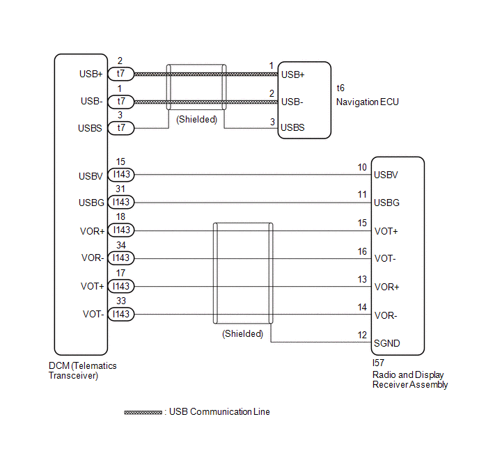
This circuit is used to send and receive signals between the DCM (telematics transceiver) and radio and display receiver assembly.
WIRING DIAGRAM
PROCEDURE
|
1. |
CHECK HARNESS AND CONNECTOR (RADIO AND DISPLAY RECEIVER ASSEMBLY - DCM (TELEMATICS TRANSCEIVER)) |
(a) Disconnect the I143 DCM (telematics transceiver) connector.
(b) Disconnect the I57 radio and display receiver assembly connector.
(c) Measure the resistance according to the value(s) in the table below.
Standard Resistance:
|
Tester Connection |
Condition |
Specified Condition |
|---|---|---|
|
I143-31 (USBG) - I57-11 (USBG) |
Always |
Below 1 Ω |
|
I143-17 (VOT+) - I57-13 (VOR+) |
Always |
Below 1 Ω |
|
I143-15 (USBV) - I57-10 (USBV) |
Always |
Below 1 Ω |
|
I143-33 (VOT-) - I57-14 (VOR-) |
Always |
Below 1 Ω |
|
I143-34 (VOR-) - I57-16 (VOT-) |
Always |
Below 1 Ω |
|
I143-18 (VOR+) - I57-15 (VOT+) |
Always |
Below 1 Ω |
|
I143-31 (USBG) or I57-11 (USBG) - Body ground |
Always |
10 kΩ or higher |
|
I143-17 (VOT+) or I57-13 (VOR+) - Body ground |
Always |
10 kΩ or higher |
|
I143-15 (USBV) or I57-10 (USBV) - Body ground |
Always |
10 kΩ or higher |
|
I143-33 (VOT-) or I57-14 (VOR-) - Body ground |
Always |
10 kΩ or higher |
|
I143-34 (VOR-) or I57-16 (VOT-) - Body ground |
Always |
10 kΩ or higher |
|
I143-18 (VOR+) or I57-15 (VOT+) - Body ground |
Always |
10 kΩ or higher |
| NG |

|
REPAIR OR REPLACE HARNESS OR CONNECTOR |
|

|
2. |
CHECK HARNESS AND CONNECTOR (NAVIGATION ECU - DCM (TELEMATICS TRANSCEIVER)) |
|
(a) Disconnect the t6 navigation ECU connector. |
|
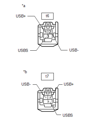
(b) Disconnect the t7 DCM (telematics transceiver) connector.
(c) Measure the resistance according to the value(s) in the table below.
Standard Resistance:
|
Tester Connection |
Condition |
Specified Condition |
|---|---|---|
|
t6-1 (USB+) - t7-2 (USB+) |
Always |
Below 1 Ω |
|
t6-2 (USB-) - t7-1 (USB-) |
Always |
Below 1 Ω |
|
t6-3 (USBS) - t7-3 (USBS) |
Always |
Below 1 Ω |
|
t6-1 (USB+) or t7-2 (USB+) - Body ground |
Always |
10 kΩ or higher |
|
t6-2 (USB-) or t7-1 (USB-) - Body ground |
Always |
10 kΩ or higher |
|
t6-3 (USBS) or t7-3 (USBS) - Body ground |
Always |
10 kΩ or higher |
| OK |
|
PROCEED TO NEXT SUSPECTED AREA SHOWN IN PROBLEM SYMPTOMS TABLE |
| NG |
|
REPAIR OR REPLACE HARNESS OR CONNECTOR |
|
|
|