| Last Modified: 05-13-2024 | 6.11:8.1.0 | Doc ID: RM1000000026JDC |
| Model Year Start: 2023 | Model: Corolla Hatchback | Prod Date Range: [09/2022 - 11/2022] |
| Title: M20A-FKS (ENGINE CONTROL): SFI SYSTEM: ECM Power Source Circuit; 2023 MY Corolla Corolla Hatchback [09/2022 - 11/2022] | ||
|
ECM Power Source Circuit |
DESCRIPTION
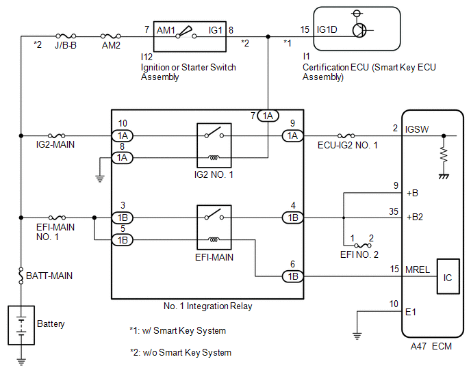
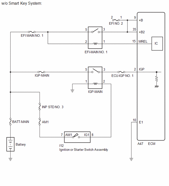
When the ignition switch is turned to ON, the battery voltage is applied to the IGSW*1 or IGP*2 terminal of the ECM. The output signal from the MREL terminal of the ECM causes current to flow to the coil of the No. 1 integration relay (EFI-MAIN relay)*1 or EFI-MAIN NO. 1*2, closing the contacts of the EFI-MAIN relay*1 or EFI-MAIN NO. 1 relay*2 and supplying power to terminals +B and +B2 of the ECM.
- *1: for TMMMS Made
- *2: for TMC Made
WIRING DIAGRAM
for TMMMS Made
for TMC Made
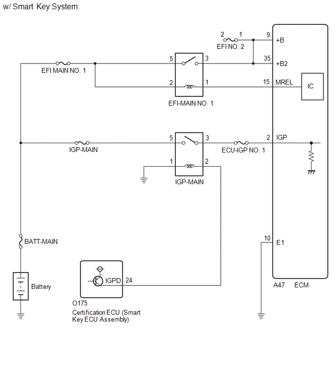
for TMC Made
CAUTION / NOTICE / HINT
NOTICE:
Inspect the fuses for circuits related to this system before performing the following procedure.
PROCEDURE
|
1. |
CHECK VEHICLE SPECIFICATION |
(a) Check the vehicle specification
|
Result |
Proceed to |
|---|---|
|
for TMMMS Made |
A |
|
for TMC Made |
B |
| B |

|
|

|
2. |
CHECK HARNESS AND CONNECTOR (POWER SOURCE OF NO. 1 INTEGRATION RELAY) |
(a) Disconnect the No. 1 integration relay connector.
(b) Measure the voltage according to the value(s) in the table below.
Standard Voltage:
|
Tester Connection |
Condition |
Specified Condition |
|---|---|---|
|
1A-10 - Body ground |
Always |
11 to 14 V |
|
1B-3 - Body ground |
Always |
11 to 14 V |
|
1B-5 - Body ground |
Always |
11 to 14 V |
| NG |
|
REPAIR OR REPLACE HARNESS OR CONNECTOR (BATTERY - NO. 1 INTEGRATION RELAY) |
|
|
3. |
INSPECT NO. 1 INTEGRATION RELAY (EFI-MAIN RELAY, IG2 NO. 1 RELAY) |
(a) Inspect the No. 1 integration relay (EFI-MAIN relay, IG2 NO. 1 relay).
Click here
![2023 MY Corolla Corolla Hatchback Corolla HV GR Corolla [09/2022 - 11/2022]; POWER DISTRIBUTION: INTEGRATION RELAY: INSPECTION](/t3Portal/stylegraphics/info.gif)
| NG |
|
REPLACE NO. 1 INTEGRATION RELAY |
|
|
4. |
CHECK HARNESS AND CONNECTOR (NO. 1 INTEGRATION RELAY - ECM) |
(a) Disconnect the No. 1 integration relay connector.
(b) Disconnect the ECM connector.
(c) Remove the EFI-MAIN NO. 2 relay and EFI-MAIN NO. 3 relay from the No. 1 engine room relay block and No. 1 junction block assembly.
HINT:
Remove the EFI-MAIN NO. 2 and EFI-MAIN NO. 3 relays connected between the checked terminals as the coil inside the relay influences the measurement value.
(d) Remove the VVT relay from No. 2 relay block assembly.
HINT:
Remove the VVT relay connected between the checked terminals as the coil inside the relay influences the measurement value.
(e) Measure the resistance according to the value(s) in the table below.
Standard Resistance:
|
Tester Connection |
Condition |
Specified Condition |
|---|---|---|
|
1A-9 - A47-2 (IGSW) |
Always |
Below 1 Ω |
|
1B-6 - A47-15 (MREL) |
Always |
Below 1 Ω |
|
1B-4 - A47-9 (+B) |
Always |
Below 1 Ω |
|
1B-4 - A47-35 (+B2) |
Always |
Below 1 Ω |
|
1A-9 or A47-2 (IGSW) - Body ground and other terminals |
Always |
10 kΩ or higher |
|
1B-6 or A47-15 (MREL) - Body ground and other terminals |
Always |
10 kΩ or higher |
|
1B-4 or A47-9 (+B) - Body ground and other terminals |
Always |
10 kΩ or higher |
|
1B-4 or A47-35 (+B2) - Body ground and other terminals |
Always |
10 kΩ or higher |
HINT:
If a short is detected in any of the above circuits, there may be a malfunction in the circuit of a connected ECU.
| NG |
|
REPAIR OR REPLACE HARNESS OR CONNECTOR |
|
|
5. |
CHECK HARNESS AND CONNECTOR (ECM - BODY GROUND) |
(a) Disconnect the ECM connector.
(b) Measure the resistance according to the value(s) in the table below.
Standard Resistance:
|
Tester Connection |
Condition |
Specified Condition |
|---|---|---|
|
A47-10 (E1) - Body ground |
Always |
Below 1 Ω |
| NG |
|
REPAIR OR REPLACE HARNESS OR CONNECTOR |
|
|
6. |
CHECK HARNESS AND CONNECTOR (NO. 1 INTEGRATION RELAY - BODY GROUND) |
(a) Disconnect the No. 1 integration relay connector.
(b) Measure the resistance according to the value(s) in the table below.
Standard Resistance:
|
Tester Connection |
Condition |
Specified Condition |
|---|---|---|
|
1A-8 - Body ground |
Always |
Below 1 Ω |
| NG |
|
REPAIR OR REPLACE HARNESS OR CONNECTOR |
|
|
7. |
CHECK TERMINAL VOLTAGE (IGSW TERMINAL VOLTAGE) |
|
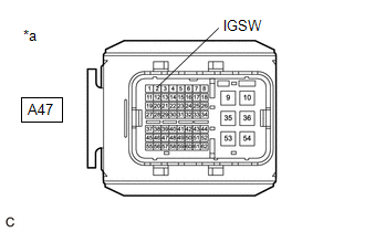
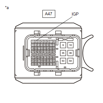
*a |
Front view of wire harness connector (to ECM) |
(a) Disconnect the ECM connector.
(b) Turn the ignition switch to ON.
(c) Measure the voltage according to the value(s) in the table below.
Standard Voltage:
|
Tester Connection |
Condition |
Specified Condition |
|---|---|---|
|
A47-2 (IGSW) - Body ground |
Ignition switch ON |
11 to 14 V |
|
Result |
Proceed to |
|---|---|
|
OK |
A |
|
NG (w/ Smart Key System) |
B |
|
NG (w/o Smart Key System) |
C |
| A |
|
PROCEED TO NEXT SUSPECTED AREA SHOWN IN PROBLEM SYMPTOMS TABLE |
| C |
|
|
|
8. |
CHECK HARNESS AND CONNECTOR (CERTIFICATION ECU (SMART KEY ECU ASSEMBLY) - NO. 1 INTEGRATION RELAY) |
(a) Disconnect the certification ECU (smart key ECU assembly) connector.
(b) Disconnect the No. 1 integration relay connector.
(c) Disconnect the instrument panel junction block assembly 4F connector.
HINT:
Disconnect the IG1-NO. 1, IG1-NO. 2 and IG2-NO. 2 relays connected between the checked terminals as the coil inside the relay influences the measurement value.
(d) Measure the resistance according to the value(s) in the table below.
Standard Resistance:
|
Tester Connection |
Condition |
Specified Condition |
|---|---|---|
|
I1-15 (IG1D) - 1A-7 |
Always |
Below 1 Ω |
|
I1-15 (IG1D) or 1A-7 - Body ground and other terminals |
Always |
10 kΩ or higher |
| OK |
|
| NG |
|
REPAIR OR REPLACE HARNESS OR CONNECTOR |
|
9. |
INSPECT IGNITION OR STARTER SWITCH ASSEMBLY |
(a) Inspect the ignition or starter switch assembly.
Click here
| NG |
|
|
|
10. |
CHECK HARNESS AND CONNECTOR (IGNITION OR STARTER SWITCH ASSEMBLY - NO. 1 INTEGRATION RELAY) |
(a) Disconnect the ignition or starter switch assembly connector.
(b) Disconnect the No. 1 integration relay connector.
(c) Disconnect the instrument panel junction block assembly 4F connector.
HINT:
Disconnect the IG1-NO. 1, IG1-NO. 2 and IG2-NO. 2 relays connected between the checked terminals as the coil inside the relay influences the measurement value.
(d) Measure the resistance according to the value(s) in the table below.
Standard Resistance:
|
Tester Connection |
Condition |
Specified Condition |
|---|---|---|
|
I12-8 (IG1) - 1A-7 |
Always |
Below 1 Ω |
|
I12-8 (IG1) or 1A-7 - Body ground and other terminals |
Always |
10 kΩ or higher |
| OK |
|
REPAIR OR REPLACE HARNESS OR CONNECTOR (BATTERY - IGNITION OR STARTER SWITCH ASSEMBLY) |
| NG |
|
REPAIR OR REPLACE HARNESS OR CONNECTOR |
|
11. |
CHECK HARNESS AND CONNECTOR (ECM - BODY GROUND) |
(a) Disconnect the ECM connector.
(b) Measure the resistance according to the value(s) in the table below.
Standard Resistance:
|
Tester Connection |
Condition |
Specified Condition |
|---|---|---|
|
A47-10 (E1) - Body ground |
Always |
Below 1 Ω |
| NG |
|
REPAIR OR REPLACE HARNESS OR CONNECTOR |
|
|
12. |
CHECK TERMINAL VOLTAGE (IGP TERMINAL VOLTAGE) |
(a) Disconnect the ECM connector.
(b) Turn the ignition switch to ON.
|
(c) Measure the voltage according to the value(s) in the table below. Standard Voltage:
|
|
| NG |
|
|
|
13. |
INSPECT EFI-MAIN NO. 1 RELAY |
Click here
| NG |
|
REPLACE EFI-MAIN NO. 1 RELAY |
|
|
14. |
CHECK HARNESS AND CONNECTOR (EFI-MAIN NO. 1 RELAY - ECM) |
(a) Disconnect the ECM connector.
(b) Remove the EFI-MAIN NO. 1 relay, EFI-MAIN NO. 3 relay and EDU relay from the No. 1 engine room relay block and No. 1 junction block assembly.
HINT:
Remove the EFI-MAIN NO. 2 VVT, and EFI-MAIN NO. 3 relays connected between the checked terminals as the coil inside the relay influences the measurement value.
(c) Measure the resistance according to the value(s) in the table below.
Standard Resistance:
|
Tester Connection |
Condition |
Specified Condition |
|---|---|---|
|
1(EFI-MAIN NO.1 relay) - A47-15 (MREL) |
Always |
Below 1 Ω |
|
3(EFI-MAIN NO.1 relay) - A47-9 (+B) |
Always |
Below 1 Ω |
|
3(EFI-MAIN NO.1 relay) - A47-35 (+B2) |
Always |
Below 1 Ω |
|
1(EFI-MAIN NO.1 relay) or A47-15 (MREL) - Body ground and other terminals |
Always |
10 kΩ or higher |
|
1(EFI-MAIN NO.1 relay), A47-15(MREL), A47-9 (+B) or A47-35 (+B2) - Body ground and other terminals |
Always |
10 kΩ or higher |
| NG |
|
REPAIR OR REPLACE HARNESS OR CONNECTOR |
|
|
15. |
CHECK TERMINAL VOLTAGE (POWER SOURCE OF EFI-MAIN NO. 1 RELAY) |
|
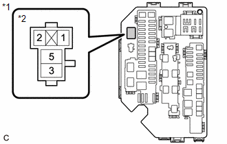
*1 |
No. 1 Engine Room Relay Block and No. 1 Junction Block Assembly |
|
*2 |
EFI-MAIN NO. 1 Relay |
(a) Remove the EFI-MAIN NO. 1 relay from the No. 1 engine room relay block and No. 1 junction block assembly.
(b) Measure the voltage according to the value(s) in the table below.
Standard Voltage:
|
Tester Connection |
Condition |
Specified Condition |
|---|---|---|
|
2(EFI-MAIN NO. 1 relay) - Body ground |
Always |
11 to 14 V |
|
5(EFI-MAIN NO. 1 relay) - Body ground |
Always |
11 to 14 V |
| OK |
|
| NG |
|
REPAIR OR REPLACE HARNESS OR CONNECTOR (BATTERY - EFI-MAIN NO. 1 RELAY) |
|
16. |
INSPECT IGP-MAIN RELAY |
Click here
| NG |
|
REPLACE IGP-MAIN RELAY |
|
|
17. |
CHECK HARNESS AND CONNECTOR (IGP-MAIN RELAY - ECM) |
(a) Disconnect the ECM connector.
(b) Remove the IGP-MAIN relay from the No. 1 engine room relay block and No. 1 junction block assembly.
(c) Measure the resistance according to the value(s) in the table below.
Standard Resistance:
|
Tester Connection |
Condition |
Specified Condition |
|---|---|---|
|
3(IGP-MAIN relay) - A47-2 (IGP) |
Always |
Below 1 Ω |
|
3(IGP-MAIN relay) or A47-2 (IGP) - Body ground and other terminals |
Always |
10 kΩ or higher |
| NG |
|
REPAIR OR REPLACE HARNESS OR CONNECTOR |
|
|
18. |
CHECK HARNESS AND CONNECTOR (POWER SOURCE VOLTAGE OF IGP-MAIN RELAY) |
|
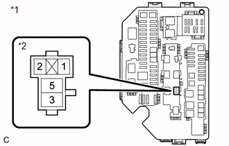
*1 |
No. 1 Engine Room Relay Block and No. 1 Junction Block Assembly |
|
*2 |
IGP-MAIN Relay |
(a) Remove the IGP-MAIN relay from the No. 1 engine room relay block and No. 1 junction block assembly.
(b) Measure the voltage according to the value(s) in the table below.
Standard Voltage:
|
Tester Connection |
Condition |
Specified Condition |
|---|---|---|
|
5(IGP-MAIN relay) - Body ground |
Always |
11 to 14 V |
| NG |
|
REPAIR OR REPLACE HARNESS OR CONNECTOR (BATTERY - IGP-MAIN RELAY) |
|
|
19. |
CHECK HARNESS AND CONNECTOR (IGP RELAY - BODY GROUND) |
(a) Remove the IGP-MAIN relay from the No. 1 engine room relay block and No. 1 junction block assembly.
(b) Measure the resistance according to the value(s) in the table below.
Standard Resistance:
|
Tester Connection |
Condition |
Specified Condition |
|---|---|---|
|
1(IGP-MAIN relay) - Body ground |
Always |
Below 1 Ω |
|
Result |
Proceed to |
|---|---|
|
OK (w/ Smart Key System) |
A |
|
OK (w/o Smart Key System) |
B |
|
NG |
C |
| B |
|
| C |
|
REPAIR OR REPLACE HARNESS OR CONNECTOR |
|
|
20. |
CHECK HARNESS AND CONNECTOR (CERTIFICATION ECU - IGP-MAIN RELAY) |
(a) Disconnect the certification ECU (smart key ECU assembly) connector.
(b) Remove the IGP-MAIN relay from the No. 1 engine room relay block and No. 1 junction block assembly.
(c) Measure the resistance according to the value(s) in the table below.
Standard Resistance:
|
Tester Connection |
Condition |
Specified Condition |
|---|---|---|
|
O175-24 (IGPD) - 2(IGP-MAIN relay) |
Always |
Below 1 Ω |
|
O175-24 (IGPD) or 2(IGP-MAIN relay) - Body ground and other terminals |
Always |
10 kΩ or higher |
| OK |
|
GO TO SMART KEY SYSTEM for TMMMS Made: Click here
for TMC Made: Click here
|
| NG |
|
REPAIR OR REPLACE HARNESS OR CONNECTOR |
|
21. |
INSPECT IGNITION OR STARTER SWITCH ASSEMBLY |
(a) Inspect the ignition or starter switch assembly.
Click here
| NG |
|
|
|
22. |
CHECK HARNESS AND CONNECTOR (IGNITION OR STARTER SWITCH ASSEMBLY - IGP-MAIN RELAY) |
(a) Disconnect the ignition or starter switch assembly connector.
(b) Remove the IGP-MAIN relay from the No. 1 engine room relay block and No. 1 junction block assembly.
(c) Measure the resistance according to the value(s) in the table below.
Standard Resistance:
|
Tester Connection |
Condition |
Specified Condition |
|---|---|---|
|
I12-8 (IG1) - 2 (IGP-MAIN relay) |
Always |
Below 1 Ω |
|
I12-8 (IG1) or 2 (IGP-MAIN relay) - Body ground and other terminals |
Always |
10 kΩ or higher |
| OK |
|
REPAIR OR REPLACE HARNESS OR CONNECTOR (BATTERY - IGNITION OR STARTER SWITCH ASSEMBLY) |
| NG |
|
REPAIR OR REPLACE HARNESS OR CONNECTOR |
|
|
|