- LIN communication system
- Steering lock ECU (steering lock actuator or upper bracket assembly)
- Certification ECU (smart key ECU assembly)
- Wire harness or connector
| Last Modified: 05-13-2024 | 6.11:8.1.0 | Doc ID: RM1000000026DYR |
| Model Year Start: 2023 | Model: GR Corolla | Prod Date Range: [09/2022 - 11/2022] |
| Title: THEFT DETERRENT / KEYLESS ENTRY: SMART KEY SYSTEM (for Start Function (Gasoline Model, except TMMMS Made)): B228562; Steering Lock Position Signal Compare Failure; 2023 MY Corolla Corolla Hatchback GR Corolla [09/2022 - 11/2022] | ||
|
DTC |
B228562 |
Steering Lock Position Signal Compare Failure |
DESCRIPTION
except Manual Transaxle
-
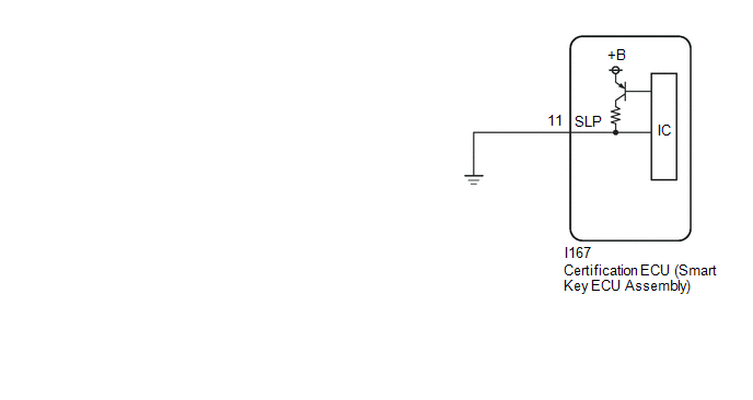
This DTC is stored when there is no continuity between terminal SLP of the certification ECU (smart key ECU assembly) and ground.
DTC No.
Detection Item
DTC Detection Condition
Trouble Area
Note
B228562
Steering Lock Position Signal Compare Failure
This DTC is stored when there is no continuity between terminal SLP of the certification ECU (smart key ECU assembly) and ground.
- Certification ECU (smart key ECU assembly)
- Wire harness or connector
DTC Output Confirmation Operation:
- Disconnect the cable from the negative (-) auxiliary battery terminal, wait 30 seconds and then reconnect the cable to the negative (-) auxiliary battery terminal. Wait at least 40 seconds with the ignition switch off, then turn the ignition switch to ON and wait at least 40 seconds.
*: Only detected while a malfunction is present and the ignition switch is ON.
Vehicle Condition and Fail-safe Function when Malfunction Detected
Vehicle Condition when Malfunction Detected
Fail-safe Function when Malfunction Detected
The engine cannot be started.
The ECU does not send an engine start request.
Related Data List and Active Test Items
DTC No.
Data List and Active Test
B228562
-
for Manual Transaxle
-
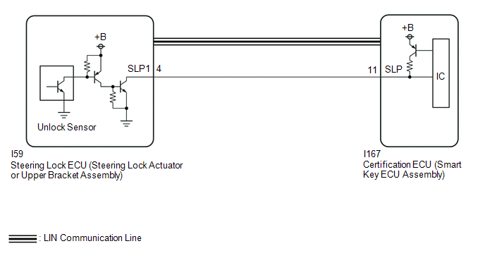
This DTC is stored when the steering lock position signal sent by the steering lock ECU (steering lock actuator or upper bracket assembly) via direct line and the steering lock position signal sent via LIN communication do not match.
DTC No.
Detection Item
DTC Detection Condition
Trouble Area
Note
B228562
Steering Lock Position Signal Compare Failure
The steering lock position signal sent by the steering lock ECU (steering lock actuator or upper bracket assembly) via direct line and the steering lock position signal sent via LIN communication do not match. (1-trip detection logic*)
DTC Output Confirmation Operation:
- Disconnect the cable from the negative (-) auxiliary battery terminal, wait 30 seconds and then reconnect the cable to the negative (-) auxiliary battery terminal. Wait at least 40 seconds with the ignition switch off (wait is the steering locked), then turn the ignition switch to ON (steering unlocked) and wait at least 40 seconds.
*: Only detected while a malfunction is present and the ignition switch is ON.
Vehicle Condition and Fail-safe Function when Malfunction Detected
Vehicle Condition when Malfunction Detected
Fail-safe Function when Malfunction Detected
The engine cannot be started.
The ECU does not send an engine start request.
Related Data List and Active Test Items
DTC No.
Data List and Active Test
B228562
Power Source Control
- Steering Unlock Switch
Smart Key
- Power Supply Short History
- Motor Driver Short History
- Lock Bar Stuck Error History
WIRING DIAGRAM
except Manual Transaxle
for Manual Transaxle
CAUTION / NOTICE / HINT
NOTICE:
-
When using the GTS with the ignition switch off, connect the GTS to the DLC3 and turn a courtesy light switch on and off at intervals of 1.5 seconds or less until communication between the GTS and the vehicle begins.
Then select Model Code "KEY REGIST" under manual mode and enter the following menus: Body Electrical / Start Key(CAN). While using the GTS, periodically turn a courtesy light switch on and off at intervals of 1.5 seconds or less to maintain communication between the GTS and the vehicle.
-
The smart key system (for Start Function) uses the LIN communication system and CAN communication system. Inspect the communication function by following How to Proceed with Troubleshooting. Troubleshoot the smart key system (for Start Function) after confirming that the communication systems are functioning properly.
Click here
![2023 MY Corolla Corolla Hatchback GR Corolla [09/2022 - 11/2022]; THEFT DETERRENT / KEYLESS ENTRY: SMART KEY SYSTEM (for Start Function (Gasoline Model, except TMMMS Made)): HOW TO PROCEED WITH TROUBLESHOOTING](/t3Portal/stylegraphics/info.gif)
- Inspect the fuses for circuits related to this system before performing the following procedure.
-
Before replacing the certification ECU (smart key ECU assembly) or steering lock ECU (steering lock actuator or upper bracket assembly)*, refer to Registration.
Click here
- *: for Manual Transaxle
- After repair, confirm that no DTCs are output by performing "DTC Output Confirmation Operation".
PROCEDURE
|
1. |
SYSTEM CHECK |
(a) Check the vehicle specification.
|
Result |
Proceed to |
|---|---|
|
for Manual Transaxle |
A |
|
except Manual Transaxle |
B |
| B |

|
|

|
2. |
CHECK FOR DTC |
(a) Check for DTCs.
Body Electrical > Smart Key > Trouble Codes
HINT:
- If the steering cannot be unlocked, the ignition switch cannot be turned to ON and the engine cannot be started.
- If LIN communication is not available, the steering cannot be locked or unlocked.
|
Result |
Proceed to |
|---|---|
|
B278588 is not output |
A |
|
B278588 is output |
B |
| B |
|
|
|
3. |
READ VALUE USING GTS (STEERING UNLOCK SWITCH) |
(a) Read the Data List according to the display on the GTS.
Body Electrical > Power Source Control > Data List
|
Tester Display |
Measurement Item |
Range |
Normal Condition |
Diagnostic Note |
|---|---|---|---|---|
|
Steering Unlock Switch |
State of steering unlock sensor signal output from steering lock ECU (steering lock actuator or upper bracket assembly) |
OFF or ON |
OFF: Steering locked |
|
Body Electrical > Power Source Control > Data List
|
Tester Display |
|---|
|
Steering Unlock Switch |
OK:
The GTS display changes.
|
Result |
Proceed to |
|---|---|
|
The value of Steering Unlock Switch is OFF |
A |
|
The value of Steering Unlock Switch is not OFF |
B |
| B |
|
REPLACE STEERING LOCK ECU (STEERING LOCK ACTUATOR OR UPPER BRACKET ASSEMBLY) |
|
|
4. |
READ VALUE USING GTS (STEERING UNLOCK SWITCH) |
(a) Read the Data List according to the display on the GTS.
Body Electrical > Power Source Control > Data List
|
Tester Display |
Measurement Item |
Range |
Normal Condition |
Diagnostic Note |
|---|---|---|---|---|
|
Steering Unlock Switch |
State of steering unlock sensor signal output from steering lock ECU (steering lock actuator or upper bracket assembly) |
OFF or ON |
ON: Steering unlocked |
|
Body Electrical > Power Source Control > Data List
|
Tester Display |
|---|
|
Steering Unlock Switch |
OK:
The GTS display changes.
|
Result |
Proceed to |
|---|---|
|
The value of Steering Unlock Switch is ON |
A |
|
The value of Steering Unlock Switch is not ON |
B |
| B |
|
REPLACE STEERING LOCK ECU (STEERING LOCK ACTUATOR OR UPPER BRACKET ASSEMBLY) |
|
|
5. |
CHECK STEERING LOCK ECU (STEERING LOCK ACTUATOR OR UPPER BRACKET ASSEMBLY) |
|
(a) Measure the resistance according to the value(s) in the table below. Standard Resistance:
HINT:
Result:
|
|
| NG |
|
REPLACE STEERING LOCK ECU (STEERING LOCK ACTUATOR OR UPPER BRACKET ASSEMBLY) |
|
|
6. |
CHECK HARNESS AND CONNECTOR (CERTIFICATION ECU (SMART KEY ECU ASSEMBLY) - STEERING LOCK ECU (STEERING LOCK ACTUATOR OR UPPER BRACKET ASSEMBLY)) |
Pre-procedure1
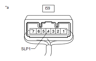
(a) Disconnect the I167 certification ECU (smart key ECU assembly) connector.
(b) Disconnect the I59 steering lock ECU (steering lock actuator or upper bracket assembly) connector.
Procedure1
(c) Measure the resistance according to the value(s) in the table below.
Standard Resistance:
|
Tester Connection |
Condition |
Specified Condition |
|---|---|---|
|
I167-11 (SLP) - I59-4 (SLP1) |
Always |
Below 1 Ω |
|
I167-11 (SLP) or I59-4 (SLP1) - Other terminals and body ground |
Always |
10 kΩ or higher |
Post-procedure1
(d) None
| OK |
|
| NG |
|
REPAIR OR REPLACE HARNESS OR CONNECTOR |
|
7. |
CHECK FOR DTC |
(a) Check for DTCs.
Body Electrical > Smart Key > Trouble Codes
|
Result |
Proceed to |
|---|---|
|
B278588 is not output |
A |
|
B278588 is output |
B |
| B |
|
|
|
8. |
CHECK HARNESS AND CONNECTOR (CERTIFICATION ECU (SMART KEY ECU ASSEMBLY) - BODY GROUND) |
(a) Disconnect the I167 certification ECU (smart key ECU assembly) connector.
(b) Measure the resistance according to the value(s) in the table below.
Standard Resistance:
|
Tester Connection |
Condition |
Specified Condition |
|---|---|---|
|
I167-11 (SLP) - Body ground |
Always |
Below 1 Ω |
| OK |
|
| NG |
|
REPAIR OR REPLACE HARNESS OR CONNECTOR |
|
|
|