| Last Modified: 05-13-2024 | 6.11:8.1.0 | Doc ID: RM1000000026D5X |
| Model Year Start: 2023 | Model: GR Corolla | Prod Date Range: [09/2022 - 11/2022] |
| Title: NETWORKING: LIN COMMUNICATION SYSTEM (except TMC Made): B2325; LIN Communication Bus Malfunction; 2023 MY Corolla Corolla Hatchback Corolla HV GR Corolla [09/2022 - 11/2022] | ||
|
DTC |
B2325 |
LIN Communication Bus Malfunction |
DESCRIPTION
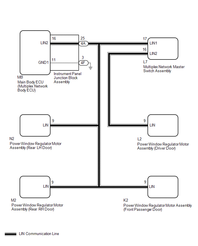
If the main body ECU (multiplex network body ECU) detects a communication error with an ECU connected to the door bus lines for 8 seconds or more, DTC B2325 will be stored.
|
DTC No. |
Detection Item |
DTC Detection Condition |
Trouble Area |
|---|---|---|---|
|
B2325 |
LIN Communication Bus Malfunction |
The main body ECU (multiplex network body ECU) detects a communication error with an ECU connected to the door bus lines for 8 seconds or more. |
|
WIRING DIAGRAM
CAUTION / NOTICE / HINT
NOTICE:
-
When a power window regulator motor assembly is replaced or removed and reinstalled, it is necessary to perform initialization.
Click here
![2023 MY Corolla Corolla Hatchback Corolla HV GR Corolla [09/2022 - 11/2022]; WINDOW / GLASS: POWER WINDOW CONTROL SYSTEM (except TMC Made): INITIALIZATION](/t3Portal/stylegraphics/info.gif)
-
Before replacing the main body ECU (multiplex network body ECU), refer to Registration.
Click here
PROCEDURE
|
1. |
CHECK POWER WINDOW REGULATOR MOTOR ASSEMBLY (DRIVER DOOR) |
(a) Disconnect the L2 power window regulator motor assembly (driver door) connector.
(b) Clear the DTCs.
Body Electrical > Main Body > Clear DTCs
(c) After 10 seconds have elapsed, check if the same DTC is output again.
Body Electrical > Main Body > Trouble Codes
|
Result |
Proceed to |
|---|---|
|
DTC B2325 is output |
A |
|
DTC B2325 is not output |
B |
| B |

|
|

|
2. |
CHECK MULTIPLEX NETWORK MASTER SWITCH ASSEMBLY |
(a) Disconnect the L7 multiplex network master switch assembly connector.
(b) Clear the DTCs.
Body Electrical > Main Body > Clear DTCs
(c) After 10 seconds have elapsed, check if the same DTC is output again.
Body Electrical > Main Body > Trouble Codes
|
Result |
Proceed to |
|---|---|
|
DTC B2325 is output |
A |
|
DTC B2325 is not output |
B |
| B |
|
|
|
3. |
CHECK POWER WINDOW REGULATOR MOTOR ASSEMBLY (FRONT PASSENGER DOOR) |
(a) Disconnect the K2 power window regulator motor assembly (front passenger door) connector.
(b) Clear the DTCs.
Body Electrical > Main Body > Clear DTCs
(c) After 10 seconds have elapsed, check if the same DTC is output again.
Body Electrical > Main Body > Trouble Codes
|
Result |
Proceed to |
|---|---|
|
DTC B2325 is output |
A |
|
DTC B2325 is not output |
B |
| B |
|
REPLACE POWER WINDOW REGULATOR MOTOR ASSEMBLY (FRONT PASSENGER DOOR) |
|
|
4. |
CHECK POWER WINDOW REGULATOR MOTOR ASSEMBLY (REAR RH DOOR) |
(a) Disconnect the M2 power window regulator motor assembly (rear RH door) connector.
(b) Clear the DTCs.
Body Electrical > Main Body > Clear DTCs
(c) After 10 seconds have elapsed, check if the same DTC is output again.
Body Electrical > Main Body > Trouble Codes
|
Result |
Proceed to |
|---|---|
|
DTC B2325 is output |
A |
|
DTC B2325 is not output |
B |
| B |
|
REPLACE POWER WINDOW REGULATOR MOTOR ASSEMBLY (REAR RH DOOR) |
|
|
5. |
CHECK POWER WINDOW REGULATOR MOTOR ASSEMBLY (REAR LH DOOR) |
(a) Disconnect the N2 power window regulator motor assembly (rear LH door) connector.
(b) Clear the DTCs.
Body Electrical > Main Body > Clear DTCs
(c) After 10 seconds have elapsed, check if the same DTC is output again.
Body Electrical > Main Body > Trouble Codes
|
Result |
Proceed to |
|---|---|
|
DTC B2325 is output |
A |
|
DTC B2325 is not output |
B |
| B |
|
REPLACE POWER WINDOW REGULATOR MOTOR ASSEMBLY (REAR LH DOOR) |
|
|
6. |
CHECK HARNESS AND CONNECTOR (INSTRUMENT PANEL JUNCTION BLOCK ASSEMBLY - EACH ECU) |
(a) Disconnect the 4A instrument panel junction block assembly connector.
(b) Measure the resistance according to the value(s) in the table below.
Standard Resistance:
|
Tester Connection |
Condition |
Specified Condition |
|---|---|---|
|
4A-25 - Body ground |
Always |
10 kΩ or higher |
(c) Disconnect all other connectors in the same circuit.
(d) Measure the resistance according to the value(s) in the table below.
Standard Resistance:
|
Tester Connection |
Condition |
Specified Condition |
|---|---|---|
|
4A-25 - Other terminals |
Always |
10 kΩ or higher |
| NG |
|
REPAIR OR REPLACE HARNESS OR CONNECTOR |
|
|
7. |
INSPECT INSTRUMENT PANEL JUNCTION BLOCK ASSEMBLY |
(a) Remove the instrument panel junction block assembly.
Click here
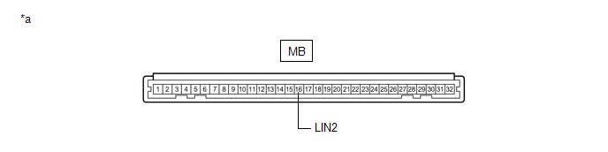
(b) Remove the main body ECU (multiplex network body ECU) from the instrument panel junction block assembly.
|
*a |
Component without harness connected (Instrument Panel Junction Block Assembly) |
- |
- |
(c) Measure the resistance according to the value(s) in the table below.
HINT:
This inspection is to check the LIN communication line in the instrument panel junction block assembly that connects the wire harness to the built-in main body ECU (multiplex network body ECU).
Standard Resistance:
|
Tester Connection |
Condition |
Specified Condition |
|---|---|---|
|
MB-16 (LIN2) - Other terminals |
Always |
10 kΩ or higher |
| NG |
|
|
|
8. |
CHECK MAIN BODY ECU (MULTIPLEX NETWORK BODY ECU) |
(a) Install the main body ECU (multiplex network body ECU) to the instrument panel junction block assembly.
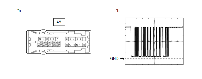
(b) Connect all instrument panel junction block assembly connectors other than 4F and 4A.
|
*a |
Component without harness connected (Instrument Panel Junction Block Assembly) |
*b |
Waveform |
(c) Using a Techstream, check the waveform.
HINT:
This inspection is to check the LIN communication line in the instrument panel junction block assembly that connects the wire harness to the built-in main body ECU (multiplex network body ECU).
OK:
|
Tester Connection |
Condition |
Tool Setting |
Specified Condition |
|---|---|---|---|
|
4A-25 - Body ground |
Power switch on (IG) |
2 V/DIV., 200 ms/DIV. |
Pulse generation (See waveform) |
| OK |
|
| NG |
|
|
9. |
CHECK HARNESS AND CONNECTOR (MULTIPLEX NETWORK MASTER SWITCH ASSEMBLY - POWER WINDOW REGULATOR MOTOR ASSEMBLY (DRIVER DOOR)) |
(a) Measure the resistance according to the value(s) in the table below.
Standard Resistance:
|
Tester Connection |
Condition |
Specified Condition |
|---|---|---|
|
L7-16 (LIN2) - Body ground |
Always |
10 kΩ or higher |
|
L7-16 (LIN2) - Other terminals |
Always |
10 kΩ or higher |
| OK |
|
| NG |
|
REPAIR OR REPLACE HARNESS OR CONNECTOR |
|
|
|