- Poor idle, etc.
- Engine start function, etc.
| Last Modified: 05-13-2024 | 6.11:8.1.0 | Doc ID: RM100000002698R |
| Model Year Start: 2023 | Model: GR Corolla | Prod Date Range: [09/2022 - 11/2022] |
| Title: G16E-GTS (EMISSION CONTROL): CANISTER: REMOVAL; 2023 MY GR Corolla [09/2022 - 11/2022] | ||
REMOVAL
CAUTION / NOTICE / HINT
The necessary procedures (adjustment, calibration, initialization, or registration) that must be performed after parts are removed and installed, or replaced during the charcoal canister assembly removal/installation are shown below.
Necessary Procedures After Parts Removed/Installed/Replaced
|
Replaced Part or Performed Procedure |
Necessary Procedure |
Effect/Inoperative Function when Necessary Procedure not Performed |
Link |
|---|---|---|---|
|
Replacement of 4WD linear solenoid (electro magnetic control coupling sub-assembly) |
ECU Data Write (When replacing 4WD linear solenoid (electro magnetic control coupling sub-assembly)) |
Active Torque Split AWD System |
|
|
Gas leak from exhaust system is repaired |
Inspection after repair |
|
|
|
Rear wheel alignment adjustment |
|
|
|
|
Tire |
ECU Data Initialization (When performing tire replacement after RoB code X2104 is output) |
Active Torque Split AWD System |
|
CAUTION:
-
Never perform work on fuel system components near any possible ignition sources.
- Vaporized fuel could ignite, resulting in a serious accident.
-
Do not perform work on fuel system components without first disconnecting the cable from the negative (-) battery terminal.
- Sparks could cause vaporized fuel to ignite, resulting in a serious accident.
HINT:
When the cable is disconnected / reconnected to the battery terminal, systems temporarily stop operating. However, each system has a function that completes learning the first time the system is used.
Learning completes when vehicle is driven
|
Effect/Inoperative Function when Necessary Procedure not Performed |
Necessary Procedure |
Link |
|---|---|---|
|
Front Camera System (for TMC Made) |
Drive the vehicle straight ahead at 35 km/h (22 mph) or more for 5 seconds or more. |
|
Learning completes when vehicle is operated normally
|
Effect/Inoperative Function when Necessary Procedure not Performed |
Necessary Procedure |
Link |
|---|---|---|
|
Power Door Lock Control System
|
Perform door unlock operation with door control switch or electrical key transmitter sub-assembly switch. |
|
PROCEDURE
1. REMOVE FUEL TANK SUB-ASSEMBLY
Click here
![2023 MY GR Corolla [09/2022 - 11/2022]; G16E-GTS (FUEL): FUEL TANK: REMOVAL](/t3Portal/stylegraphics/info.gif)
2. DISCONNECT FUEL TANK VENT HOSE SUB-ASSEMBLY
NOTICE:
- Remove any dirt or foreign matter on the tube connector before performing this work.
- Do not allow any scratches or foreign matter to get on the parts when disconnecting them as the tube connector has an O-ring that seals the pipe (canister (charcoal canister assembly)).
- Perform this work by hand. Do not use any tools.
- Do not forcibly bend, twist or turn the fuel tank vent hose.
- Protect the disconnected parts by covering them with plastic bags after disconnecting the fuel tank vent hose.
- If the tube connector and pipe (canister (charcoal canister assembly)) are stuck, push and pull to release them.
|
*a |
Retainer |
*b |
Tab |
|
*c |
Tube Connector |
*d |
O-ring |
|
*e |
Pipe (Canister (Charcoal Canister Assembly)) |
- |
- |

|
Pinch |

|
Pull |

|
Pull off |
- |
- |
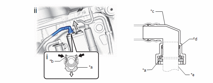
(1) Pinch the tabs of the retainer to disengage the lock claws and pull it down.
HINT:
Do not remove the retainer.
(2) Pull off the fuel tank vent hose sub-assembly from the canister (charcoal canister assembly).
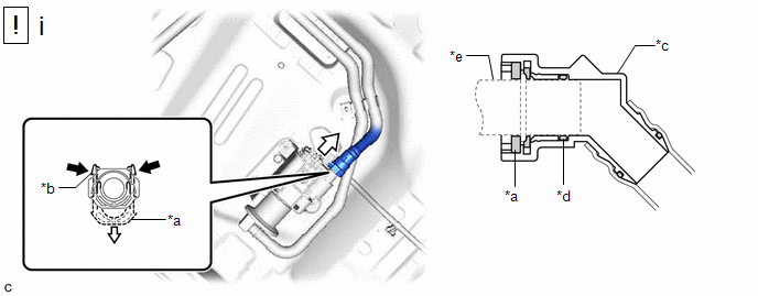
3. DISCONNECT VENT LINE HOSE
NOTICE:
- Remove any dirt or foreign matter on the tube connector before performing this work.
- Do not allow any scratches or foreign matter to get on the parts when disconnecting them as the tube connector has an O-ring that seals the pipe (canister (charcoal canister assembly)).
- Perform this work by hand. Do not use any tools.
- Do not forcibly bend, twist or turn the vent line hose.
- Protect the disconnected parts by covering them with plastic bags after disconnecting the vent line hose.
- If the tube connector and pipe (canister (charcoal canister assembly)) are stuck, push and pull to release them.
|
*1 |
Vent Line Hose |
*2 |
Pipe (Canister (Charcoal Canister Assembly)) |
|
*a |
Retainer |
*b |
Tab |
|
*c |
Tube Connector |
*d |
O-ring |
|
*e |
Pipe (Canister (Charcoal Canister Assembly)) |
- |
- |
|
|
Pinch |
|
Pull |
|
|
Pull off |
- |
- |
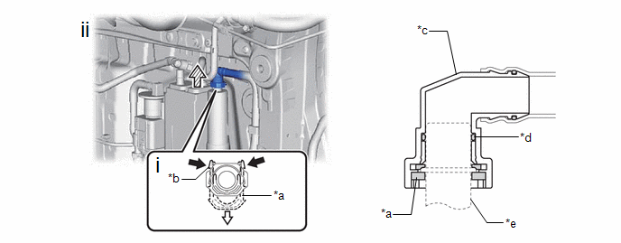
(1) Pinch the tabs of the retainer to disengage the lock claws and pull it down.
HINT:
Do not remove the retainer.
(2) Pull off the vent line hose from the canister (charcoal canister assembly).
4. DISCONNECT FUEL EMISSION HOSE

5. REMOVE CANISTER (CHARCOAL CANISTER ASSEMBLY)
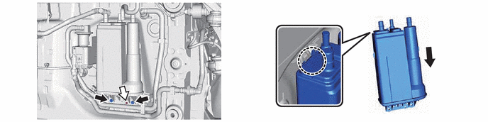
6. REMOVE CHARCOAL CANISTER OUTLET GUIDE

7. REMOVE AIR LINE HOSE
NOTICE:
- Remove any dirt or foreign matter on the tube connector before performing this work.
- Do not allow any scratches or foreign matter to get on the parts when disconnecting them as the tube connector has an O-ring that seals the pipe (leak detection pump sub-assembly).
- Perform this work by hand. Do not use any tools.
- Do not forcibly bend, twist or turn the air line tube.
- Protect the disconnected parts by covering them with plastic bags after disconnecting the air line tube.
- If the tube connector and pipe (leak detection pump sub-assembly) are stuck, push and pull to release them.
|
*1 |
Air Line Tube |
*2 |
Pipe (Leak Detection Pump Sub-assembly) |
|
*a |
Retainer |
*b |
Tab |
|
*c |
Tube Connector |
*d |
O-ring |
|
*e |
Pipe (Leak Detection Pump Sub-assembly) |
- |
- |
|
|
Pinch |
|
Pull |
(1) Push the retainer and pull off the air line tube.
HINT:
Do not remove the retainer.
8. REMOVE NO. 2 CHARCOAL CANISTER SUB-ASSEMBLY

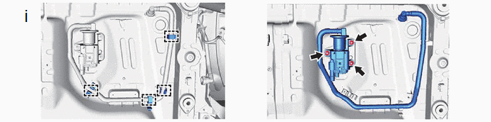
(1) Disconnect the 4 clamps.
9. REMOVE LEAK DETECTION PUMP SUB-ASSEMBLY
HINT:
Only perform this procedure when replacement of the leak detection pump sub-assembly is necessary.
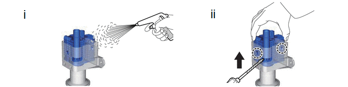
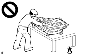
(1) Before removing the leak detection pump sub-assembly, clean the No. 2 charcoal canister sub-assembly by blowing air into it to ensure that the No. 2 charcoal canister sub-assembly is free of foreign matter.
NOTICE:
- Make sure to clean the No. 2 charcoal canister sub-assembly using air only.
- Do not use gasoline, thinners or solvents.
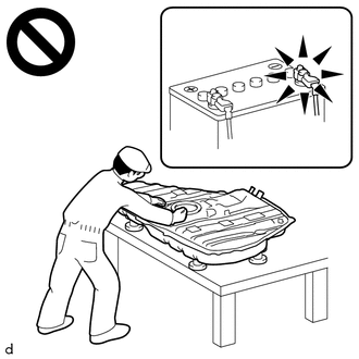
(2) While disengaging the 2 claws as shown in the illustration, push the leak detection pump sub-assembly upwards using a screwdriver with its tip wrapped with protective tape to remove it.

(1) Check if the No. 2 charcoal canister sub-assembly contains foreign matter such as mud or water.
- Visually check that the inside of the No. 2 charcoal canister sub-assembly is free of foreign matter.
-
Hold the No. 2 charcoal canister sub-assembly upside down to make sure that it is free of foreign matter.
If the No. 2 charcoal canister sub-assembly contains foreign matter, replace it.
|
|
|