- Perform "Reset Memory"
- Perform "Calibration"
| Last Modified: 01-27-2025 | 6.11:8.1.0 | Doc ID: RM1000000026944 |
| Model Year Start: 2023 | Model: GR Corolla | Prod Date Range: [09/2022 - ] |
| Title: AXLE AND DIFFERENTIAL: REAR AXLE CARRIER (for AWD with Electric Parking Brake): REMOVAL; 2023 - 2025 MY Corolla Corolla Hatchback Corolla HV GR Corolla [09/2022 - ] | ||
REMOVAL
CAUTION / NOTICE / HINT
The necessary procedures (adjustment, calibration, initialization, or registration) that must be performed after parts are removed and installed, or replaced during rear axle carrier sub-assembly removal/installation are shown below.
Necessary Procedures After Procedure Performed
|
Replaced Part or Performed Procedure |
Necessary Procedure |
Effect/Inoperative Function when Necessary Procedure not Performed |
Link |
|---|---|---|---|
|
Rear wheel alignment adjustment |
|
|
|
CAUTION / NOTICE / HINT
HINT:
- Use the same procedure for the RH side and LH side.
- The following procedure is for the LH side.
PROCEDURE
1. REMOVE REAR WHEEL
Click here
![2023 - 2025 MY Corolla Corolla Hatchback Corolla HV GR Corolla [09/2022 - ]; MAINTENANCE: TIRE AND WHEEL: REMOVAL](/t3Portal/stylegraphics/info.gif)
2. REMOVE REAR AXLE SHAFT NUT
Click here
3. SEPARATE NO. 2 PARKING BRAKE WIRE ASSEMBLY
|
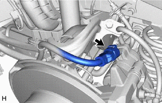
(a) Disconnect the No. 2 parking brake wire assembly connector from the parking brake actuator assembly. NOTICE:
|
|
|
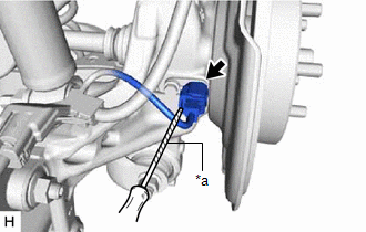
(b) Using a screwdriver with its tip wrapped with protective tape, disconnect the No. 2 parking brake wire assembly connector from the rear skid control sensor. NOTICE: Be careful not to damage the rear skid control sensor or connector cover. |
|
|
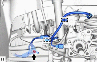
(c) Remove the nut, disengage the 2 clamps and separate the No. 2 parking brake wire assembly from the rear flexible hose bracket and rear trailing arm assembly. |
|
4. REMOVE REAR SKID CONTROL SENSOR
Click here
5. SEPARATE REAR FLEXIBLE HOSE
|
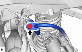
(a) Remove the bolt and separate the rear flexible hose from the rear flexible hose bracket. |
|
6. SEPARATE REAR DISC BRAKE CALIPER ASSEMBLY
Click here
7. REMOVE REAR DISC
Click here
8. REMOVE REAR AXLE HUB AND BEARING ASSEMBLY
Click here
9. REMOVE REAR FLEXIBLE HOSE BRACKET
|
(a) Remove the bolt and rear flexible hose bracket from the rear axle carrier sub-assembly. |
|
10. REMOVE REAR STABILIZER LINK ASSEMBLY
Click here
11. REMOVE REAR COIL SPRING
Click here
12. REMOVE REAR LOWER COIL SPRING INSULATOR
Click here
13. REMOVE REAR NO. 1 SUSPENSION ARM ASSEMBLY
Click here
14. REMOVE REAR AXLE CARRIER SUB-ASSEMBLY
|
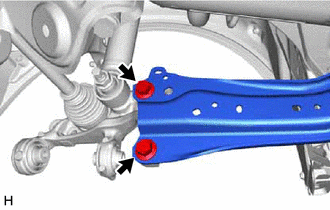
(a) Loosen the 2 bolts of the rear trailing arm assembly. |
|
|
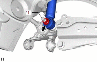
(b) Loosen the nut of the rear shock absorber assembly. NOTICE: Hold the rear axle carrier pin while rotating the nut. |
|
|
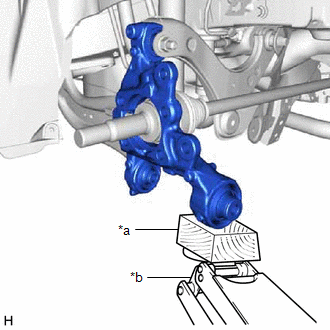
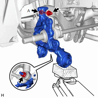
(c) Using a jack and a wooden block, support the rear axle carrier sub-assembly. NOTICE:
|
|
|
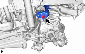
(d) Loosen the bolt (A). NOTICE: Because the nut has its own stopper, do not turn the nut. Loosen the bolt with the nut secured. |
|
(e) Remove the 2 bolts and separate the rear trailing arm assembly from the rear axle carrier sub-assembly.
(f) Remove the nut and plate washer, and separate the rear shock absorber assembly from the rear axle carrier sub-assembly.
NOTICE:
Hold the rear axle carrier pin while rotating the nut.
(g) Remove the bolt (A), nut and rear axle carrier sub-assembly from the rear upper control arm assembly.
NOTICE:
Because the nut has its own stopper, do not turn the nut. Loosen the bolt with the nut secured.
NOTICE:
- Because the nut has its own stopper, do not turn the nut. Loosen the bolt with the nut secured.
- Use wire or an equivalent tool to keep the rear drive shaft assembly from hanging down.
|
|
|