| Last Modified: 05-13-2024 | 6.11:8.1.0 | Doc ID: RM100000002693B |
| Model Year Start: 2023 | Model: GR Corolla | Prod Date Range: [09/2022 - ] |
| Title: AXLE AND DIFFERENTIAL: REAR AXLE HUB (for AWD without Electric Parking Brake): REMOVAL; 2023 - 2025 MY Corolla Corolla Hatchback Corolla HV GR Corolla [09/2022 - ] | ||
REMOVAL
CAUTION / NOTICE / HINT
The necessary procedures (adjustment, calibration, initialization, or registration) that must be performed after parts are removed and installed, or replaced during rear axle hub and bearing assembly removal/installation are shown below.
Necessary Procedures After Parts Removed/Installed/Replaced
|
Replaced Part or Performed Procedure |
Necessary Procedure |
Effect/Inoperative Function when Necessary Procedure not Performed |
Link |
|---|---|---|---|
|
Tire |
ECU Data Initialization (When performing tire replacement after RoB code X2104 is output) |
Active Torque Split AWD System |
NOTICE:
-
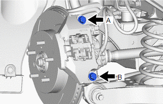
To avoid degrading the precision of the assembly, do not loosen or remove the 2 bolts shown in the illustration.
-
If the bolts have been loosened or removed, use the following procedure to reassemble the parts.
- Temporarily install the rear disc brake cylinder assembly with the 2 bolts.
- Start the engine.
- Depress the brake pedal to continuously apply hydraulic pressure.
- Temporarily tighten bolt A to 30 N*m (306 kgf*cm, 22 ft.*lbf).
- Temporarily tighten bolt B to 30 N*m (306 kgf*cm, 22 ft.*lbf).
- Fully tighten bolt A to 70 N*m (714 kgf*cm, 52 ft.*lbf).
- Fully tighten bolt B to 70 N*m (714 kgf*cm, 52 ft.*lbf).
- Release the brake pedal to release the hydraulic pressure.
- Check that the 2 bolts are tightened to 70 N*m (714 kgf*cm, 52 ft.*lbf).
HINT:
- Use the same procedure for the RH side and LH side.
- The following procedure is for the LH side.
PROCEDURE
1. REMOVE REAR WHEEL
2. REMOVE REAR AXLE SHAFT NUT
|
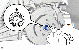
(a) Using SST and a hammer, release the staked part of the rear axle shaft nut. SST: 09930-00010 NOTICE: Loosen the staked part of the rear axle shaft nut completely, otherwise the threads of the rear drive shaft assembly may be damaged. |
|
(b) While applying the brakes, using a 30 mm deep socket wrench, remove the rear axle shaft nut.
3. SEPARATE REAR SPEED SENSOR
|
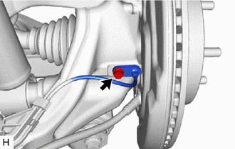
(a) Remove the bolt and separate the rear speed sensor from the rear axle carrier sub-assembly. NOTICE:
|
|
4. SEPARATE REAR DISC BRAKE CALIPER ASSEMBLY
5. REMOVE DISK WHEEL SPACER
6. REMOVE PARKING BRAKE SHOE ADJUSTING HOLE PLUG
7. REMOVE REAR DISC
8. REMOVE REAR AXLE HUB AND BEARING ASSEMBLY
|
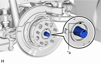
(a) Put matchmarks on the rear drive shaft assembly and rear axle hub and bearing assembly. |
|
|
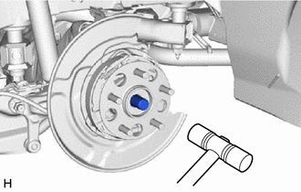
(b) Using a plastic hammer, separate the rear drive shaft assembly from the rear axle hub and bearing assembly. HINT: If it is difficult to separate the rear drive shaft assembly from the rear axle hub and bearing assembly, tap the end of the rear drive shaft assembly using a brass bar and a hammer. |
|
|
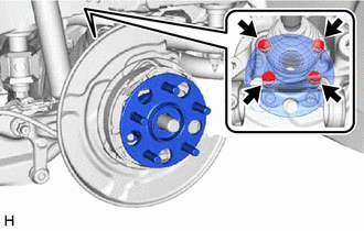
(c) Remove the 4 bolts, rear axle hub and bearing assembly and rear disc brake dust cover sub-assembly from the rear axle carrier sub-assembly. |
|
|
|
|
![2023 - 2025 MY Corolla Corolla Hatchback GR Corolla [09/2022 - ]; GF1A (TRANSFER / 4WD / AWD): ACTIVE TORQUE SPLIT AWD SYSTEM: CALIBRATION](/t3Portal/stylegraphics/info.gif)
