| Last Modified: 01-27-2025 | 6.11:8.1.0 | Doc ID: RM10000000268JD |
| Model Year Start: 2023 | Model: GR Corolla | Prod Date Range: [09/2022 - ] |
| Title: G16E-GTS (INTAKE / EXHAUST): TURBOCHARGER: INSPECTION; 2023 - 2025 MY GR Corolla [09/2022 - ] | ||
INSPECTION
PROCEDURE
1. INSPECT TURBOCHARGER SUB-ASSEMBLY
|
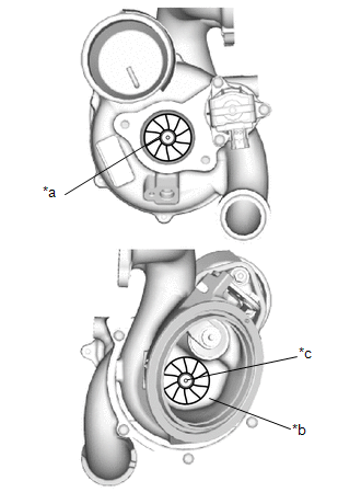
(a) Check if the compressor side impeller and exhaust side turbine are damaged or defective. HINT: Wear on the center of the exhaust side turbine is not a malfunction. |
|
|
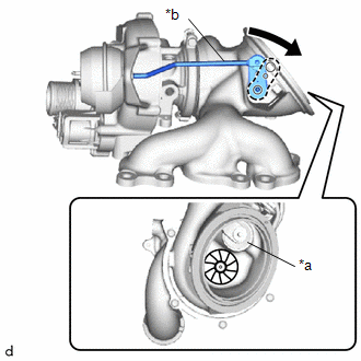
(b) Move the rod by hand and check that the waste gate valve is not stuck. |
|
|
(c) Using a straightedge and feeler gauge, check the turbocharger sub-assembly installation surface for warpage. Standard Warpage: 0.20 mm (0.0079 in.) or less If the result is not as specified, replace the turbocharger sub-assembly. |
|
|
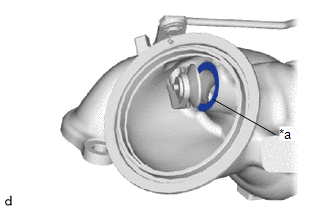
(d) Close the waste gate valve and using a feeler gauge, measure the clearance between the waste gate valve and the contact surface of the valve port of the turbine with valve housing sub-assembly waste gate. Standard Clearance: 0.15 mm (0.00591 in.) or less If the result is not as specified, replace the turbocharger sub-assembly. |
|
|
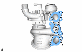
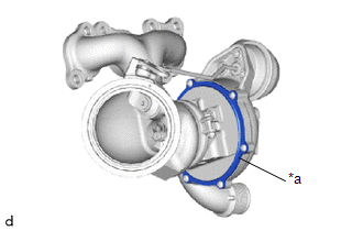
(e) Check the areas shown in the illustration for oil leakage. OK: There are no oil leaks from the compressor with bearing housing sub-assembly. NOTICE: Oil on the inlet side of the compressor is from oil in the blow-by gas and is not a malfunction. If the result is not as specified, replace the turbocharger sub-assembly. |
|
|
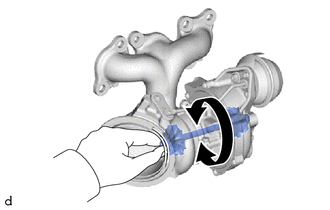
(f) Rotate the compressor wheel by hand as shown in the illustration, and check that the compressor wheel rotates smoothly. OK: Compressor wheel rotates smoothly. HINT: If the compressor wheel does not rotate smoothly, replace the turbocharger sub-assembly. |
|
(g) Check that the turbine shaft rotates smoothly.
|
(1) Set a dial indicator to the outlet side of the turbine shaft. |
|
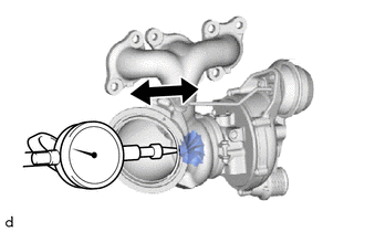
(2) Move the turbine shaft in the axial direction and check for play.
Standard Axial Play:
0.20 mm (0.0079 in.) or less
If the result is not as specified, replace the turbocharger sub-assembly.
2. INSPECT WASTE GATE VALVE ACTUATOR
(a) Check the waste gate valve actuator hose for cracks and damage.
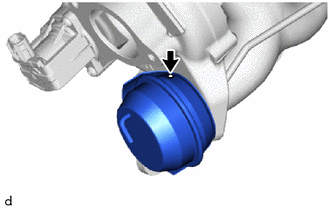
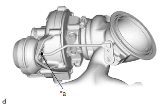
(b) Check the waste gate valve actuator with bracket assembly air hole.
|
(1) Check that the waste gate valve actuator air hole shown in the illustration is not clogged. |
|
(c) Check the waste gate valve actuator with bracket assembly travel.
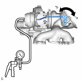
(1) Connect a vacuum pump to the waste gate valve actuator.
|
(2) Using a vacuum pump, apply a vacuum of 30 +/- 4.0 kPa (225 +/- 30 mmHg, 8.8 +/- 1.2 in. Hg) to the diaphragm chamber to operate the waste gate valve actuator. OK: The waste gate valve closes when vacuum is applied. NOTICE: Do not apply a vacuum of 65 kPa (488 mmHg, 19.2 in. Hg) or more to the waste gate valve actuator as doing so may damage the diaphragm. HINT: If the waste gate valve actuator does not operate, replace the turbocharger sub-assembly. |
|
|
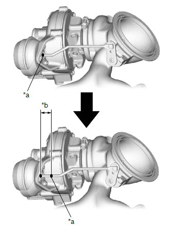
(3) Place a paint mark on the waste gate valve actuator rod from the waste gate valve actuator bracket as shown in the illustration. |
|
(4) Using a vernier caliper, measure the distance from the waste gate valve actuator bracket to the paint mark at a vacuum of 0 kPa (0 mmHg, 0 in. Hg).
|
*a |
Paint Mark |
|
*b |
Travel of Waste Gate Valve Actuator |

|
Vacuum at 0 kPa (0 mmHg, 0 in. Hg) |
Standard:
15 mm (0.591 in.) or more
If the result is not as specified, replace the turbocharger sub-assembly.
NOTICE:
If the result is not as specified when replacing the turbocharger sub-assembly, and check the travel of the waste gate valve actuator again.
(5) Disconnect the vacuum pump from the waste gate valve actuator.
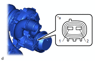
3. INSPECT INTAKE AIR CONTROL VALVE (AIR BY-PASS VALVE ASSEMBLY)
(a) Inspect the resistance.
|
(1) Measure the resistance according to the value(s) in the table below. Standard Resistance:
If the result is not as specified, replace the turbocharger sub-assembly. |
|
|
|
|