- Poor idle, etc.
- Engine start function, etc.
| Last Modified: 05-13-2024 | 6.11:8.1.0 | Doc ID: RM10000000268J1 |
| Model Year Start: 2023 | Model: GR Corolla | Prod Date Range: [09/2022 - ] |
| Title: G16E-GTS (INTAKE / EXHAUST): INTAKE SYSTEM: ON-VEHICLE INSPECTION; 2023 - 2025 MY GR Corolla [09/2022 - ] | ||
ON-VEHICLE INSPECTION
CAUTION / NOTICE / HINT
The necessary procedures (adjustment, calibration, initialization or registration) that must be performed after parts are removed and installed, or replaced when repairing air leaks in the intake system are shown below.
Necessary Procedures After Parts Removed/Installed/Replaced
|
Replaced Part or Performed Procedure |
Necessary Procedure |
Effect/Inoperative Function when Necessary Procedure not Performed |
Link |
|---|---|---|---|
|
Air leaks from intake system |
Inspection After Repair |
|
|
PROCEDURE
1. INSPECT INTAKE SYSTEM
CAUTION:
To prevent injury due to contact with an operating cooling fan, keep your hands and clothing away from the cooling fans when working in the engine compartment with the engine running or the engine switch on (IG).
HINT:
Perform "Inspection After Repair" after repairing vacuum leaks in the intake system.
Click here
![2023 - 2025 MY GR Corolla [09/2022 - ]; G16E-GTS (ENGINE CONTROL): SFI SYSTEM: INITIALIZATION](/t3Portal/stylegraphics/info.gif)
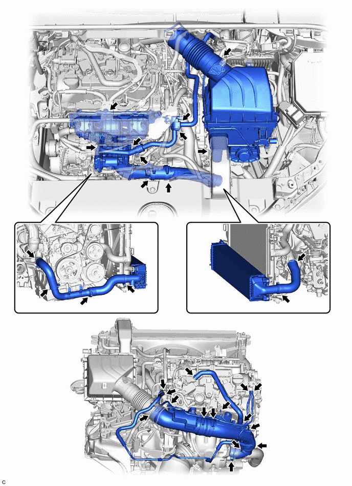
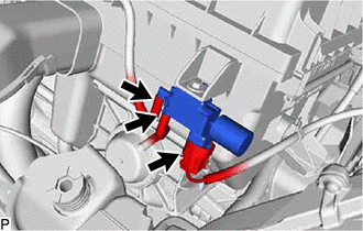
(a) Check that there are no vacuum leaks at the points shown in the illustration.
2. PERFORM INITIALIZATION
(a) Perform "Inspection After Repair" after repairing vacuum leaks in the intake system.
Click here
3. INSPECT INTAKE AIR CONTROL VALVE ACTUATOR
|
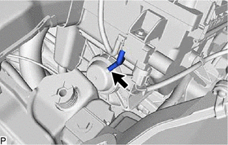
(a) Disconnect the vacuum hose from the intake air control valve actuator. |
|
|
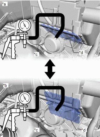
(b) Confirm that the intake air control valve opens smoothly under vacuum and closes smoothly when the vacuum is released. If the intake air control valve does not close or open smoothly, replace the air cleaner assembly. |
|
(c) Connect the vacuum hose to the intake air control valve actuator.
4. INSPECT VACUUM SWITCHING VALVE ASSEMBLY (for AICV)
|
(a) Disconnect the vacuum switching valve assembly (for AICV) connector. |
|
(b) Disconnect the 2 vacuum hoses from the vacuum switching valve assembly (for AICV).
|
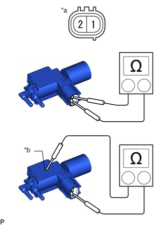
(c) Measure the resistance according to the value(s) in the table below. Standard Resistance:
If the result is not as specified, replace the air cleaner assembly. |
|
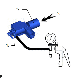
(d) Check the operation of the vacuum switching valve assembly (for AICV).
|
(1) When vacuum is applied to the port (E), check that air is sucked into the filter. If air is not sucked into the filter, replace the air cleaner assembly. |
|
|
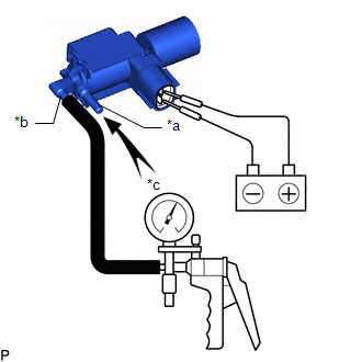
(2) Apply battery voltage across the terminals. When vacuum is applied to the port (F), check that air is sucked into the port (E). If air is not sucked into the port (F), replace the air cleaner assembly. |
|
|
|
|