| Last Modified: 05-13-2024 | 6.11:8.1.0 | Doc ID: RM10000000265TS |
| Model Year Start: 2023 | Model: GR Corolla | Prod Date Range: [09/2022 - 11/2022] |
| Title: BRAKE CONTROL / DYNAMIC CONTROL SYSTEMS: ELECTRONICALLY CONTROLLED BRAKE SYSTEM (for Gasoline Model without Electric Parking Brake System TMMMS Made): VSC OFF Switch Circuit; 2023 MY Corolla Corolla Hatchback GR Corolla [09/2022 - 11/2022] | ||
|
VSC OFF Switch Circuit |
DESCRIPTION
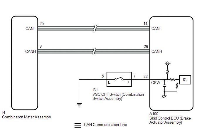
The skid control ECU (brake actuator assembly) is connected to the combination meter assembly via CAN communication.
Pressing the VSC OFF switch (combination switch assembly) turns off TRAC operation, and pressing and holding this switch turns off TRAC and VSC operation. If TRAC and VSC operations are turned off, "Traction Control Turned Off" will be displayed on the multi-information display and the VSC OFF indicator light will come on.
WIRING DIAGRAM
CAUTION / NOTICE / HINT
NOTICE:
After replacing the skid control ECU (brake actuator assembly), perform acceleration sensor zero point calibration and store system information memorization.
Click here
![2023 MY Corolla Corolla Hatchback GR Corolla [09/2022 - 11/2022]; BRAKE CONTROL / DYNAMIC CONTROL SYSTEMS: ELECTRONICALLY CONTROLLED BRAKE SYSTEM (for Gasoline Model without Electric Parking Brake System TMMMS Made): UTILITY](/t3Portal/stylegraphics/info.gif)
PROCEDURE
|
1. |
READ VALUE USING TECHSTREAM (TRAC/VSC OFF MODE) |
(a) Connect the Techstream to the DLC3.
(b) Turn the ignition switch to ON.
(c) Enter the following menus: Chassis / Brake / Data List.
Chassis > Brake > Data List
|
Tester Display |
Measurement Item |
Range |
Normal Condition |
Diagnostic Note |
|---|---|---|---|---|
|
TRC(TRAC)/VSC OFF Mode |
TRAC/VSC off mode |
Normal mode (TRC(TRAC) ON/VSC ON) / TRC(TRAC) OFF mode (TRC(TRAC) OFF/VSC ON) / Not defined / VSC OFF mode (TRC(TRAC) OFF/VSC OFF) |
Normal mode (TRC(TRAC) ON/VSC ON): Normal mode TRC(TRAC) OFF mode (TRC(TRAC) OFF/VSC ON): TRAC off mode Not defined: Not defined VSC OFF mode (TRC(TRAC) OFF/VSC OFF): VSC off mode |
- |
Chassis > Brake > Data List
|
Tester Display |
|---|
|
TRC(TRAC)/VSC OFF Mode |
(d) Check the indicator light and mode condition on the Techstream changes according to VSC OFF switch (combination switch assembly) operation.
Standard:
|
Switch Operation |
Mode Condition Display |
Multi-information Display ("Traction Control Turned Off") |
VSC OFF Indicator Light |
|---|---|---|---|
|
Not pressed |
Normal mode (TRC(TRAC) ON/VSC ON) |
Not displayed |
Does not come on |
|
Pressing the VSC OFF switch (combination switch assembly) |
TRC(TRAC) OFF mode (TRC(TRAC) OFF/VSC ON) |
Displayed |
Does not come on |
|
Pressing and holding the VSC OFF switch (combination switch assembly) |
VSC OFF mode (TRC(TRAC) OFF/VSC OFF) |
Displayed |
Comes on |
|
Result |
Proceed to |
|---|---|
|
Indicator light and mode condition display do not change |
A |
|
Mode condition display is normal, but indicator light does not change |
B |
|
Indicator light and mode condition display are normal |
C |
| B |

|
| C |
|
|

|
2. |
INSPECT COMBINATION SWITCH ASSEMBLY |
|
(a) Make sure that there is no looseness at the locking part and the connecting part of the connector. OK: The connector is securely connected. |
|
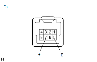
(b) Disconnect the I61 VSC OFF switch (combination switch assembly) connector.
(c) Check both the connector case and the terminal for deformation and corrosion.
OK:
No deformation or corrosion.
(d) Measure the resistance according to the value(s) in the table below.
Standard Resistance:
|
Tester Connection |
Condition |
Specified Condition |
|---|---|---|
|
7 (+) - 5 (E) |
Switch pushed |
Below 50 Ω |
|
7 (+) - 5 (E) |
Switch not pushed |
10 kΩ or higher |
| NG |
|
|
|
3. |
CHECK HARNESS AND CONNECTOR (BRAKE ACTUATOR ASSEMBLY - COMBINATION SWITCH ASSEMBLY) |
(a) Make sure that there is no looseness at the locking part and the connecting part of the connector.
OK:
The connector is securely connected.
(b) Disconnect the A100 skid control ECU (brake actuator assembly) connector.
(c) Disconnect the I61 VSC OFF switch (combination switch assembly) connector.
(d) Check both the connector case and the terminals for deformation and corrosion.
OK:
No deformation or corrosion.
(e) Measure the resistance according to the value(s) in the table below.
Standard Resistance:
|
Tester Connection |
Condition |
Specified Condition |
|---|---|---|
|
I61-7 (+) - A100-22 (CSW) |
Always |
Below 1 Ω |
|
I61-7 (+) or A100-22 (CSW) - Body ground |
Always |
10 kΩ or higher |
|
I61-5 (E) - Body ground |
Always |
Below 1 Ω |
| OK |
|
| NG |
|
REPAIR OR REPLACE HARNESS OR CONNECTOR |
|
|
|