| Last Modified: 05-13-2024 | 6.11:8.1.0 | Doc ID: RM10000000265SE |
| Model Year Start: 2023 | Model: GR Corolla | Prod Date Range: [09/2022 - 11/2022] |
| Title: BRAKE CONTROL / DYNAMIC CONTROL SYSTEMS: ELECTRONICALLY CONTROLLED BRAKE SYSTEM (for Gasoline Model without Electric Parking Brake System TMMMS Made): TERMINALS OF ECU; 2023 MY Corolla Corolla Hatchback GR Corolla [09/2022 - 11/2022] | ||
TERMINALS OF ECU
TERMINALS OF ECU
|
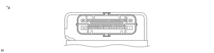
*a |
Component without harness connected (Skid Control ECU (Brake Actuator Assembly)) |
- |
- |
HINT:
- As a waterproof connector is used for the brake actuator assembly, voltage and waveform inspections cannot be performed with the connector connected.
-
Use the Techstream to read data and perform Active Tests when inspecting the operation and communication status of the brake actuator assembly.
Click here
![2023 MY Corolla Corolla Hatchback GR Corolla [09/2022 - 11/2022]; BRAKE CONTROL / DYNAMIC CONTROL SYSTEMS: ELECTRONICALLY CONTROLLED BRAKE SYSTEM (for Gasoline Model without Electric Parking Brake System TMMMS Made): DATA LIST / ACTIVE TEST](/t3Portal/stylegraphics/info.gif)
|
Terminal No. (Symbol) |
Terminal Description |
|---|---|
|
1 (+BM) |
ABS motor relay power supply |
|
2 (SP1) |
Speed signal output |
|
3 (STPO) |
Stop light control relay (stop light switch assembly) output |
|
4 (FR-) |
Front wheel speed RH (-) signal input |
|
5 |
- |
|
6 |
- |
|
7 |
- |
|
8 (FL-) |
Front wheel speed LH (-) signal input |
|
9 (STP) |
Stop light switch assembly signal input |
|
10 |
- |
|
11 |
- |
|
12 |
- |
|
13 (GND2) |
Pump motor ground |
|
14 (CANL) |
CAN communication line L |
|
15 |
- |
|
16 (FR+) |
Front wheel speed RH (+) power supply output |
|
17 (RR+) |
Rear wheel speed RH (+) power supply output |
|
18 (RL-) |
Rear wheel speed LH (-) signal input |
|
19 (FL+) |
Front wheel speed LH (+) power supply output |
|
20 |
- |
|
21 |
- |
|
22 (CSW) |
VSC OFF switch (combination switch assembly) input |
|
23 |
- |
|
24 (STP2) |
Stop light signal input |
|
25 (+BS) |
ABS solenoid relay power supply |
|
26 (CANH) |
CAN communication line H |
|
27 |
- |
|
28 (IG1) |
IG1 power source input |
|
29 (RR-) |
Rear wheel speed RH (-) signal input |
|
30 |
- |
|
31 (RL+) |
Rear wheel speed LH (+) power supply output |
|
32 |
- |
|
33 |
- |
|
34 |
- |
|
35 |
- |
|
36 |
- |
|
37 |
- |
|
38 (GND1) |
Skid control ECU (brake actuator assembly) ground |
TERMINAL INSPECTION
(a) Disconnect the A100 skid control ECU (brake actuator assembly) connector and measure the voltage and resistance on the wire harness side.
|
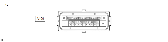
*a |
Front view of wire harness connector (to Skid Control ECU (Brake Actuator Assembly)) |
- |
- |
(b) Measure the voltage or resistance according to the value(s) in the table below.
Standard
|
Terminal No. (Symbol) |
Wiring Color |
Terminal Description |
Condition |
Specified Condition |
|---|---|---|---|---|
|
A100-1 (+BM) - Body ground |
L - Body ground |
ABS motor relay power supply |
Always |
11 to 14 V |
|
A100-3 (STPO) - Body ground |
BE - Body ground |
Stop light control relay (stop light switch assembly) output |
Always |
11 to 14 V |
|
A100-9 (STP) - Body ground |
B - Body ground |
Stop light switch assembly signal input |
Stop light switch assembly on → off (Brake pedal depressed → released) |
11 to 14 V → 1.5 V or less |
|
A100-13 (GND2) - Body ground |
W-B - Body ground |
Pump motor ground |
Always |
Below 1 Ω |
|
A100-22 (CSW) - Body ground |
BR - Body ground |
VSC OFF switch (combination switch assembly) input |
VSC OFF switch (combination switch assembly) on → off (Pressed → not pressed) |
Below 50 Ω → 10 kΩ or higher |
|
A100-24 (STP2) - Body ground |
L - Body ground |
Stop light signal input |
Stop light switch assembly on → off (Brake pedal depressed → released) |
11 to 14 V → 1.5 V or less |
|
A100-25 (+BS) - Body ground |
W - Body ground |
ABS solenoid relay power supply |
Always |
11 to 14 V |
|
A100-28 (IG1) - Body ground |
SB - Body ground |
IG1 power source input |
Ignition switch ON |
11 to 14 V |
|
A100-38 (GND1) - Body ground |
W-B - Body ground |
Skid control ECU (brake actuator assembly) ground |
Always |
Below 1 Ω |
|
|
|