- Perform "Reset Memory"
- Perform "Calibration"
| Last Modified: 01-27-2025 | 6.11:8.1.0 | Doc ID: RM10000000265FQ |
| Model Year Start: 2023 | Model: Corolla | Prod Date Range: [09/2022 - ] |
| Title: BRAKE SYSTEM (OTHER): BRAKE PEDAL (for HV Model): REMOVAL; 2023 - 2025 MY Corolla Corolla HV [09/2022 - ] | ||
REMOVAL
CAUTION / NOTICE / HINT
The necessary procedures (adjustment, calibration, initialization, or registration) that must be performed after parts are removed, installed, or replaced during brake pedal support assembly removal/installation are shown below.
Necessary Procedures After Parts Removed/Installed/Replaced
|
Replaced Part or Performed Procedure |
Necessary Procedure |
Effect/Inoperative Function when Necessary Procedure not Performed |
Link |
|---|---|---|---|
|
Removal/installation/replacement of brake pedal support assembly |
|
|
|
HINT:
When the cable is disconnected / reconnected to the auxiliary battery terminal, systems temporarily stop operating. However, each system has a function that completes learning the first time the system is used.
Items for which learning is completed by driving the vehicle
|
Effect/Inoperative Function when Necessary Procedure not Performed |
Necessary Procedures |
Link |
|---|---|---|
|
Front Camera System |
Drive the vehicle straight ahead at 15 km/h (9 mph) or more for 1 second or more. |
|
NOTICE:
- After the ignition switch is turned off, the radio and display receiver assembly records various types of memory and settings. As a result, after turning the ignition switch off, make sure to wait at least 3 minutes before disconnecting the cable from the negative (-) auxiliary battery terminal.
- When the cable is disconnected from the negative (-) auxiliary battery terminal and the security lock setting has been enabled, multi-display operations will be disabled upon next startup unless the password is entered. Be sure to check the security lock setting before disconnecting the cable from the negative (-) auxiliary battery terminal. (for Audio and Visual System (for 8 Inch Display Type (w/ Single Knob Type) or 10.5 Inch Display Type))
PROCEDURE
1. REMOVE LOWER NO. 1 INSTRUMENT PANEL AIRBAG ASSEMBLY
Click here
![2023 MY Corolla Corolla Hatchback Corolla HV GR Corolla [09/2022 - 11/2022]; SUPPLEMENTAL RESTRAINT SYSTEMS: KNEE AIRBAG ASSEMBLY: REMOVAL](/t3Portal/stylegraphics/info.gif)
2. REMOVE FRONT NO. 1 CONSOLE BOX INSERT
except G16E-GTS: Click here
for G16E-GTS: Click here
3. REMOVE NO. 1 AIR DUCT
Click here
4. REMOVE BRAKE PEDAL STROKE SENSOR ASSEMBLY
Click here
5. REMOVE STOP LIGHT SWITCH ASSEMBLY
Click here
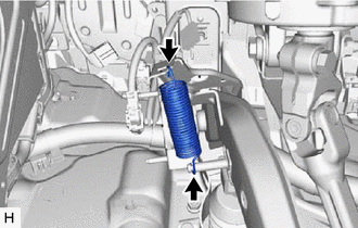
6. REMOVE BRAKE PEDAL RETURN SPRING
|
(a) Remove the brake pedal return spring from the brake pedal support assembly and push rod pin. |
|
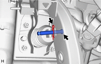
7. REMOVE PUSH ROD PIN
|
(a) Remove the clip and push rod pin to separate the brake pedal support assembly from the brake master cylinder push rod clevis. |
|
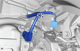
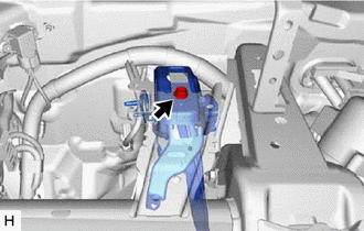
8. REMOVE BRAKE PEDAL SUPPORT ASSEMBLY
|
(a) Disengage the clamp to separate the wire harness from the brake pedal support assembly. |
|
|
(b) Remove the bolt and separate the brake pedal support assembly from the instrument panel reinforcement assembly. |
|
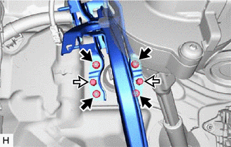
(c) Remove the 2 clips.

|
Nut |

|
Clip |
(d) Remove the 4 nuts and brake pedal support assembly.
|
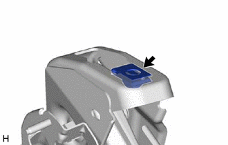
(e) Remove the nut from the brake pedal support assembly. |
|
9. REMOVE STOP LIGHT SWITCH MOUNTING ADJUSTER
|
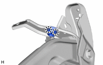
(a) Disengage the 2 claws and remove the stop light switch mounting adjuster. |
|
10. REMOVE BRAKE PEDAL PAD
(a) Remove the brake pedal pad from the brake pedal support assembly.
|
|
|