| Last Modified: 05-13-2024 | 6.11:8.1.0 | Doc ID: RM10000000264XQ |
| Model Year Start: 2023 | Model: GR Corolla | Prod Date Range: [09/2022 - 11/2022] |
| Title: NAVIGATION / MULTI INFO DISPLAY: NAVIGATION ANTENNA: INSPECTION; 2023 MY Corolla Corolla Hatchback Corolla HV GR Corolla [09/2022 - 11/2022] | ||
INSPECTION
PROCEDURE
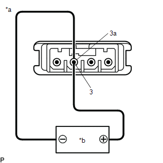
1. INSPECT NAVIGATION ANTENNA ASSEMBLY (w/o Manual (SOS) Switch)
(a) Check that the navigation antenna assembly cable is properly installed and does not have any sharp bends, pinching or loose connections.
|
(b) Current consumption check: (1) Measure the current consumption according to the value(s) in the table below. Standard Current:
NOTICE: Do not apply 6 V or more between terminals 3 and 3a. HINT: If a stable power supply is not available, connect 4 nickel-metal hydride batteries (1.2 V each) or equivalent in series. |
|

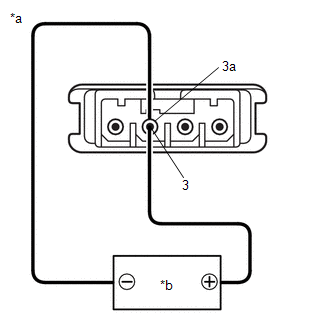
2. INSPECT NAVIGATION ANTENNA ASSEMBLY (for TMMMS Made with Manual (SOS) Switch)
(a) Check that the navigation antenna assembly cable is properly installed and does not have any sharp bends, pinching or loose connections.
|
(b) Current consumption check: (GPS) (1) Measure the current consumption according to the value(s) in the table below. Standard Current:
NOTICE: Do not apply 6 V or more between terminals 3 and 3a. HINT: If a stable power supply is not available, connect 4 nickel-metal hydride batteries (1.2 V each) or equivalent in series. |
|
|
(c) Resistance check: (Telephone Sub) (1) Measure the resistance according to the value(s) in the table below. Standard Resistance:
|
|

3. INSPECT NAVIGATION ANTENNA ASSEMBLY (for TMC Made with Manual (SOS) Switch)
(a) Check that the navigation antenna assembly cable is properly installed and does not have any sharp bends, pinching or loose connections.
(b) Current consumption check: (GPS1)
|
(1) Measure the current consumption according to the value(s) in the table below. Standard Current:
NOTICE: Do not apply 6 V or more between terminals 3 and 3a. HINT: If a stable power supply is not available, connect 4 nickel-metal hydride batteries (1.2 V each) or equivalent in series. |
|
(c) Current consumption check: (GPS2)
|
(1) Measure the current consumption according to the value(s) in the table below. Standard Current:
NOTICE: Do not apply 6 V or more between terminals 2 and 2a. HINT: If a stable power supply is not available, connect 4 nickel-metal hydride batteries (1.2 V each) or equivalent in series. |
|
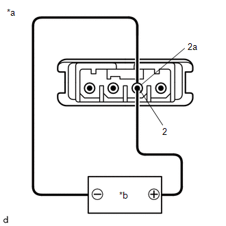
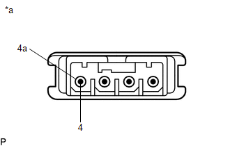
(d) Resistance check: (Telephone Sub)
|
(1) Measure the resistance according to the value(s) in the table below. Standard Resistance:
|
|
|
|
|