- Perform "Reset Memory"
- Perform "Calibration"
| Last Modified: 08-23-2025 | 6.11:8.1.0 | Doc ID: RM10000000262MB |
| Model Year Start: 2023 | Model: GR Corolla | Prod Date Range: [09/2022 - ] |
| Title: AXLE AND DIFFERENTIAL: FRONT AXLE HUB (for G16E-GTS): REMOVAL; 2023 - 2026 MY GR Corolla [09/2022 - ] | ||
REMOVAL
CAUTION / NOTICE / HINT
The necessary procedures (adjustment, calibration, initialization, or registration) that must be performed after parts are removed and installed, or replaced during front axle hub sub-assembly removal/installation are shown below.
Necessary Procedures After Parts Removed/Installed/Replaced
|
Replaced Part or Performed Procedure |
Necessary Procedure |
Effect/Inoperative Function when Necessary Procedure not Performed |
Link |
|---|---|---|---|
|
Front wheel alignment adjustment |
|
|
|
|
Tire |
ECU Data Initialization (When performing tire replacement after RoB code X2104 is output) |
Active Torque Split AWD System |
|
NOTICE:
-
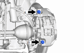
To avoid degrading the precision of the assembly, do not loosen or remove the 2 bolts shown in the illustration.
-
If the bolts have been loosened or removed, use the following procedure to reassemble the parts.
- Temporarily install the front disc brake cylinder assembly with the 2 bolts.
- Start the engine.
- Depress the brake pedal to continuously apply hydraulic pressure.
- Temporarily tighten bolt A to 30 N*m (306 kgf*cm, 22 ft.*lbf).
- Temporarily tighten bolt B to 30 N*m (306 kgf*cm, 22 ft.*lbf).
- Fully tighten bolt A to 100 N*m (1020 kgf*cm, 74 ft.*lbf).
- Fully tighten bolt B to 100 N*m (1020 kgf*cm, 74 ft.*lbf).
- Release the brake pedal to release the hydraulic pressure.
- Check that the 2 bolts are tightened to 100 N*m (1020 kgf*cm, 74 ft.*lbf).
HINT:
- Use the same procedure for the RH side and LH side.
- The following procedure is for the LH side.
PROCEDURE
1. REMOVE FRONT WHEEL
Click here
![2023 - 2026 MY Corolla Corolla Hatchback Corolla HV GR Corolla [09/2022 - ]; MAINTENANCE: TIRE AND WHEEL: REMOVAL](/t3Portal/stylegraphics/info.gif)
2. REMOVE FRONT AXLE SHAFT NUT
Click here
3. SEPARATE FRONT SPEED SENSOR
|
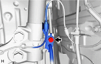
(a) Remove the bolt and separate the front speed sensor and front flexible hose from the front shock absorber assembly. NOTICE: Be sure to separate the front speed sensor and front flexible hose from the front shock absorber assembly completely. |
|
|
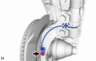
(b) Remove the bolt, disengage the clamp and separate the front speed sensor from the front shock absorber assembly and steering knuckle. NOTICE:
|
|
4. SEPARATE TIE ROD END SUB-ASSEMBLY
Click here
5. SEPARATE FRONT DISC BRAKE CALIPER ASSEMBLY
Click here
6. REMOVE FRONT DISC
Click here
7. SEPARATE FRONT LOWER NO. 1 SUSPENSION ARM SUB-ASSEMBLY
|
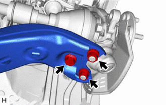
(a) Remove the bolt and 2 nuts and separate the front lower No. 1 suspension arm sub-assembly from the front lower ball joint assembly. |
|
8. SEPARATE FRONT DRIVE SHAFT ASSEMBLY
|
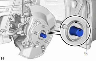
(a) Put matchmarks on the front drive shaft assembly and the front axle hub sub-assembly. |
|
|
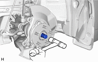
(b) Using a plastic hammer, separate the front drive shaft assembly from the front axle assembly. NOTICE:
HINT: If it is difficult to separate the front drive shaft assembly from the front axle assembly, tap the end of the front drive shaft assembly using a brass bar and a hammer. |
|
9. REMOVE FRONT AXLE ASSEMBLY
|
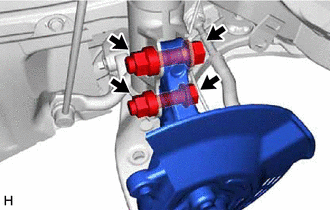
(a) Remove the 2 bolts, 2 nuts and front axle assembly from the front shock absorber assembly. NOTICE: When removing the nuts, keep the bolts from rotating. |
|
10. REMOVE FRONT AXLE HUB SUB-ASSEMBLY
|
(a) Secure the front axle assembly between aluminum plates in a vise. NOTICE: Do not overtighten the vise. |
|
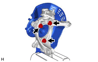
(b) Remove the 3 bolts, front axle hub sub-assembly and front disc brake dust cover from the steering knuckle.
NOTICE:
- Do not drop the front axle hub sub-assembly.
- Be careful not to damage the speed sensor rotor or contact surfaces.
- Do not allow foreign matter to contact the speed sensor rotor or contact surfaces.
|
|
|