- DTC judgment completed
- System normal
| Last Modified: 05-13-2024 | 6.11:8.1.0 | Doc ID: RM10000000262J0 |
| Model Year Start: 2023 | Model: GR Corolla | Prod Date Range: [09/2022 - ] |
| Title: G16E-GTS (ENGINE CONTROL): SFI SYSTEM: P26C518,P26C519; Exhaust Flow Control Valve "A" Control Circuit Low Circuit Current Below Threshold; 2023 - 2025 MY GR Corolla [09/2022 - ] | ||
|
DTC |
P26C518 |
Exhaust Flow Control Valve "A" Control Circuit Low Circuit Current Below Threshold |
|
DTC |
P26C519 |
Exhaust Flow Control Valve "A" Control Circuit High Circuit Current Above Threshold |
DESCRIPTION
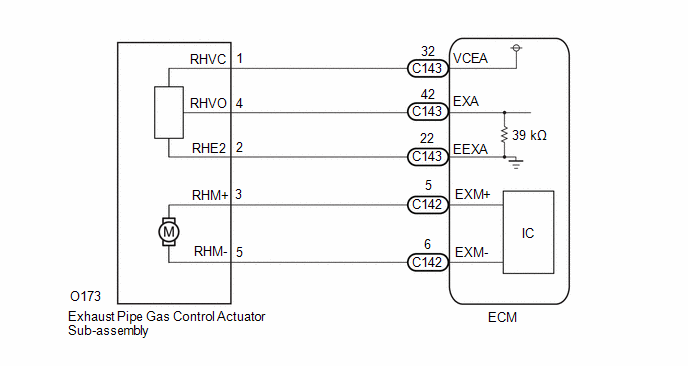
The 2-system exhaust system consists of the exhaust tailpipe assembly (exhaust change valve), exhaust pipe gas control actuator sub-assembly (drive motor and opening angle sensor) and ECM. By switching the gas flow circuit, a balance of quietness and tone is achieved and backpressure is reduced during high loads
The ECM drives the drive motor of the exhaust pipe gas control actuator sub-assembly in accordance with the driving conditions to switch the exhaust change valve open or closed.
The opening angle of the exhaust change valve is detected by the opening angle sensor of the exhaust pipe gas control actuator sub-assembly, and feedback is provided to the ECM as an exhaust valve operation status signal.
|
DTC No. |
Detection Item |
DTC Detection Condition |
Trouble Area |
MIL |
Note |
|---|---|---|---|---|---|
|
P26C518 |
Exhaust Flow Control Valve "A" Control Circuit Low Circuit Current Below Threshold |
Both of the following conditions are met for 2 seconds or more (1 trip detection logic):
|
|
Does not come on |
SAE Code: P26C6 |
|
P26C519 |
Exhaust Flow Control Valve "A" Control Circuit High Circuit Current Above Threshold |
Overcurrent cut of the exhaust pipe gas control actuator sub-assembly (drive motor) continues for 2 seconds or more (1 trip detection logic): |
|
Does not come on |
SAE Code: P26C7 |
MONITOR DESCRIPTION
The ECM monitors the current value of the exhaust pipe gas control actuator sub-assembly (drive motor), and if the current value is outside the normal range, the ECM judges that there is an exhaust pipe gas control actuator sub-assembly (drive motor) circuit malfunction.
Also, if the exhaust change valve is not functioning correctly (such as when the exhaust change valve is stuck), the ECM judges that there is a malfunction in the exhaust pipe gas control actuator sub-assembly. In this case, the ECM stores a DTC..
Example:
If the output duty cycle is 59% or more and the current flow of the exhaust pipe gas control actuator sub-assembly (drive motor) is less than 0.45 A for 2 seconds or more, the ECM judges that the value is outside the normal range and stores a DTC.
CONFIRMATION DRIVING PATTERN
P26C518
- Connect the GTS to the DLC3.
- Turn the ignition switch to ON.
- Turn the GTS on.
- Clear the DTCs (even if no DTCs are stored, perform the clear DTC procedure).
- Turn the ignition switch off and wait for at least 30 seconds.
- Turn the ignition switch to ON.
- Turn the GTS on.
- Enter the following menus: Powertrain / Engine / Active Test / Control the ExhaustSwitching Valve Position.
- In the Active Test, wait for at least 5 seconds with the exhaust change valve opening position at 0%.
- Enter the following menus: Powertrain / Engine / Trouble Codes.
-
Read the pending DTCs.
HINT:
- If a pending DTC is output, the system is malfunctioning.
- If a pending DTC is not output, perform the following procedure.
- Enter the following menus: Powertrain / Engine / Utility / All Readiness.
- Input the DTC: P26C518.
-
Check the DTC judgment result.
GTS Display
Description
NORMAL
ABNORMAL
- DTC judgment completed
- System abnormal
INCOMPLETE
- DTC judgment not completed
- Perform driving pattern after confirming DTC enabling conditions
HINT:
- If the judgment result is NORMAL, the system is normal.
- If the judgment result is ABNORMAL, the system is malfunctioning.
P26C519
- Connect the GTS to the DLC3.
- Turn the ignition switch to ON.
- Turn the GTS on.
- Clear the DTCs (even if no DTCs are stored, perform the clear DTC procedure).
- Turn the ignition switch off and wait for at least 30 seconds.
- Turn the ignition switch to ON.
- Turn the GTS on.
- Wait 5 seconds or more.
- Enter the following menus: Powertrain / Engine / Trouble Codes.
-
Read the pending DTCs.
HINT:
- If a pending DTC is output, the system is malfunctioning.
- If a pending DTC is not output, perform the following procedure.
- Enter the following menus: Powertrain / Engine / Utility / All Readiness.
- Input the DTC: P26C519.
-
Check the DTC judgment result.
GTS Display
Description
NORMAL
- DTC judgment completed
- System normal
ABNORMAL
- DTC judgment completed
- System abnormal
INCOMPLETE
- DTC judgment not completed
- Perform driving pattern after confirming DTC enabling conditions
HINT:
- If the judgment result is NORMAL, the system is normal.
- If the judgment result is ABNORMAL, the system is malfunctioning.
WIRING DIAGRAM
CAUTION / NOTICE / HINT
HINT:
Read Freeze Frame Data using the GTS. The ECM records vehicle and driving condition information as Freeze Frame Data the moment a DTC is stored. When troubleshooting, Freeze Frame Data can help determine if the vehicle was moving or stationary, if the engine was warmed up or not, if the air fuel ratio was lean or rich, and other data from the time the malfunction occurred.
PROCEDURE
|
1. |
INSPECT EXHAUST PIPE GAS CONTROL ACTUATOR SUB-ASSEMBLY |
Click here
![2023 - 2025 MY GR Corolla [09/2022 - ]; G16E-GTS (INTAKE / EXHAUST): EXHAUST PIPE GAS CONTROL ACTUATOR SUB-ASSEMBLY: ON-VEHICLE INSPECTION](/t3Portal/stylegraphics/info.gif)
| OK |

|
|

|
2. |
CHECK HARNESS AND CONNECTOR (EXHAUST PIPE GAS CONTROL ACTUATOR SUB-ASSEMBLY - ECM) |
(a) Disconnect the exhaust pipe gas control actuator sub-assembly connector.
(b) Disconnect the ECM connector.
(c) Measure the resistance according to the value(s) in the table below.
Standard Resistance:
|
Tester Connection |
Condition |
Specified Condition |
|---|---|---|
|
O173-3(RHM+) - C142-5(EXM+) |
Always |
Below 1 Ω |
|
O173-5(RHM-) - C142-6(EXM-) |
Always |
Below 1 Ω |
|
O173-3(RHM+) or C142-5(EXM+) - Body ground and other terminals |
Always |
10 kΩ or higher |
|
O173-5(RHM-) or C142-6(EXM-) - Body ground and other terminals |
Always |
10 kΩ or higher |
| NG |
|
REPAIR OR REPLACE HARNESS OR CONNECTOR |
|
|
3. |
INSPECT EXHAUST PIPE GAS CONTROL ACTUATOR SUB-ASSEMBLY |
|
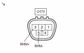
*a |
Component without harness connected (Exhaust Pipe Gas Control Actuator Sub-assembly) |
(a) Disconnect the exhaust pipe gas control actuator sub-assembly connector.
(b) Measure the resistance according to the value(s) in the table below.
Standard Resistance:
|
Tester Connection |
Condition |
Specified Condition |
|---|---|---|
|
O173-3 (RHM+) - O173-5 (RHM-) |
20°C (68°F) |
0.5 to 50 Ω |
| NG |
|
|
|
4. |
INSPECT EXHAUST TAILPIPE ASSEMBLY (EXHAUST CHANGE VALVE) |
Click here
| OK |
|
REPLACE ECM
|
| NG |
|
|
|
|