| Last Modified: 05-13-2024 | 6.11:8.1.0 | Doc ID: RM10000000261GQ |
| Model Year Start: 2023 | Model: GR Corolla | Prod Date Range: [09/2022 - ] |
| Title: POWER ASSIST SYSTEMS: POWER STEERING SYSTEM (for Gasoline Model): Drive Mode Select Switch Circuit; 2023 - 2025 MY Corolla Corolla Hatchback GR Corolla [09/2022 - ] | ||
|
Drive Mode Select Switch Circuit |
DESCRIPTION
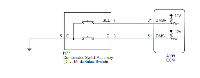
The characteristics of the electronic throttle and EPS operation change according to operation of the combination switch assembly (drivem ode select switch).
WIRING DIAGRAM
PROCEDURE
|
1. |
INSPECT COMBINATION SWITCH ASSEMBLY (DRIVE MODE SELECT SWITCH) |
|
(a) Remove the combination switch assembly (drive mode select switch). Click here
|
|
(b) Measure the resistance according to the value(s) in the table below.
Standard Resistance:
|
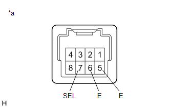
Tester Connection |
Condition |
Specified Condition |
|---|---|---|
|
7 (SEL) - 5 (E) |
Drive mode select switch pushed forward |
Below 50 Ω |
|
7 (SEL) - 5 (E) |
Drive mode select switch in neutral position |
10 kΩ or higher |
|
6 (E) - 5 (E) |
Drive mode select switch pulled rearward |
Below 50 Ω |
|
6 (E) - 5 (E) |
Drive mode select switch in neutral position |
10 kΩ or higher |
(c) Install the combination switch assembly (drive mode select switch).
Click here
![2023 - 2025 MY GR Corolla [09/2022 - ]; POWER ASSIST SYSTEMS: PATTERN SELECT SWITCH (for G16E-GTS): INSTALLATION](/t3Portal/stylegraphics/info.gif)
| NG |

|
REPLACE COMBINATION SWITCH ASSEMBLY (DRIVE MODE SELECT SWITCH) |
|

|
2. |
CHECK HARNESS AND CONNECTOR (COMBINATION SWITCH ASSEMBLY - BODY GROUND) |
(a) Disconnect the I177 combination switch assembly (drive mode select switch) connector.
(b) Measure the resistance according to the value(s) in the table below.
Standard Resistance:
|
Tester Connection |
Condition |
Specified Condition |
|---|---|---|
|
I177-5 (E) - Body ground |
Always |
Below 1 Ω |
(c) Connect the I177 combination switch assembly (drive mode select switch) connector.
| NG |
|
REPAIR OR REPLACE HARNESS OR CONNECTOR (COMBINATION SWITCH ASSEMBLY - BODY GROUND) |
|
|
3. |
CHECK HARNESS AND CONNECTOR (COMBINATION SWITCH ASSEMBLY - ECM) |
(a) Disconnect the A139 ECM connector.
(b) Measure the resistance according to the value(s) in the table below.
Standard Resistance:
|
Tester Connection |
Condition |
Specified Condition |
|---|---|---|
|
A139-31 (DMS+) - Body ground |
Drive mode select switch pushed forward |
Below 50 Ω |
|
A139-31 (DMS+) - Body ground |
Drive mode select switch in neutral position |
10 kΩ or higher |
|
A139-51 (DMS-) - Body ground |
Drive mode select switch pulled rearward |
Below 50 Ω |
|
A139-51 (DMS-) - Body ground |
Drive mode select switch in neutral position |
10 kΩ or higher |
(c) Connect the A139 ECM connector.
| OK |
|
| NG |
|
REPAIR OR REPLACE HARNESS OR CONNECTOR (COMBINATION SWITCH ASSEMBLY - ECM) |
|
|
|