- Wireless Door Lock Control System (for Gasoline Model with Smart Key System)
- Smart Key System (for Gasoline Model, Entry Function)
- Smart Key System (for Gasoline Model, Start Function)
- Steering lock function*1
| Last Modified: 05-13-2024 | 6.11:8.1.0 | Doc ID: RM10000000260U6 |
| Model Year Start: 2023 | Model: GR Corolla | Prod Date Range: [09/2022 - 11/2022] |
| Title: G16E-GTS (ENGINE MECHANICAL): CYLINDER BLOCK: DISASSEMBLY; 2023 MY GR Corolla [09/2022 - 11/2022] | ||
DISASSEMBLY
CAUTION / NOTICE / HINT
The necessary procedures (adjustment, calibration, initialization or registration) that must be performed after parts are removed and installed, or replaced during cylinder block removal/installation are shown below.
Necessary Procedure After Parts Removed/Installed/Replaced
|
Replaced Part or Performed Procedure |
Necessary Procedure |
Effect/Inoperative Function when Necessary Procedure not Performed |
Link |
|---|---|---|---|
| *1:w/ Steering Lock Function | |||
|
Replacement of ECM |
Perform Vehicle Identification Number (VIN) or frame number registration |
MIL illuminates |
|
|
ECU configuration |
- |
||
|
Update ECU security key |
Vehicle Control History (RoB) are stored |
||
|
Heavy Knock History |
- |
||
|
Code registration (Smart Key System (for Gasoline Model, Start Function)) |
|
||
|
Inspection After Repair |
|
|
|
Front wheel alignment adjustment |
|
|
|
|
Tire |
ECU Data Initialization (When performing tire replacement after RoB code X2104 is output) |
Active Torque Split AWD System |
|
NOTICE:
This procedure includes the removal of small-head bolts. Refer to Small-Head Bolts of Basic Repair Hint to identify the small-head bolts.
HINT:
When the cable is disconnected / reconnected to the auxiliary battery terminal, systems temporarily stop operating. However, each system has a function that completes learning the first time the system is used.
-
Learning completes when vehicle is driven
Effect/Inoperative Function When Necessary Procedures are not Performed
Necessary Procedures
Link
Front Camera System (for TMC Made)
Drive the vehicle straight ahead at 35 km/h (22 mph) or more for 5 seconds or more.
-
Learning completes when vehicle is operated normally
Effect/Inoperative Function When Necessary Procedures are not Performed
Necessary Procedures
Link
Power door lock control system
- Back door opener
Perform door unlock operation with door control switch or electrical key transmitter sub-assembly switch.
PROCEDURE
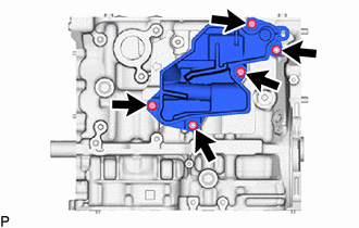
1. REMOVE NO. 1 VENTILATION CASE
CAUTION:
Do not diassembly except if the No. 1 ventilaion case to be damaged.
|
(a) Remove the 3 bolts, 2 nuts and No. 1 ventilation case from the cylinder block sub-assembly. |
|
|
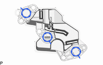
(b) Remove the 3 oil separator gaskets from the No. 1 ventilation case. |
|
2. REMOVE NO. 1 CYLINDER BLOCK INSULATOR
|
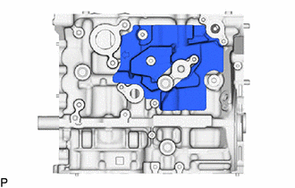
(a) Remove the No. 1 cylinder block insulator from the cylinder block sub-assembly. |
|
3. INSPECT CONNECTING ROD THRUST CLEARANCE
|
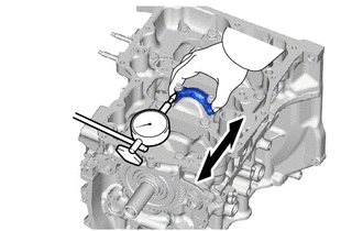
(a) Using a dial indicator, measure the thrust clearance while moving the connecting rod back and forth. Standard Thrust Clearance: 0.15 to 0.50 mm (0.00591 to 0.0197 in.) Maximum Thrust Clearance: 0.50 mm (0.0197 in.) HINT: If the thrust clearance is more than the maximum, replace the connecting rod. If necessary, replace the crankshaft. |
|
4. INSPECT CONNECTING ROD OIL CLEARANCE
|
(a) Note the alignment marks on the connecting rod and connecting rod bearing cap so that they can be reinstalled to their original locations. |
|
|
(b) Using an E12 TORX soket wrench, remove the 2 connecting rod bolts and connecting rod bearing cap. SST: 09205-16011 HINT: Keep the connecting rod bearing and connecting rod bearing cap together. |
|
(c) Clean the crank pin and connecting rod bearing.
(d) Check the crank pin and connecting rod bearing for pitting and scratches.
HINT:
If the crank pin or connecting rod bearing is damaged, replace the connecting rod bearings. If necessary, replace the crankshaft.
|
(e) Lay a strip of Plastigage on the crank pin. |
|
|
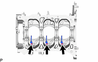
(f) Check that the front mark of the connecting rod bearing cap is facing the correct direction, and install the connecting rod bearing cap to the connecting rod. |
|
|
(g) Apply a light coat of engine oil to the threads and under the heads of the 2 connecting rod bolts. |
|
(h) Using an E12 TORX socket wrench, install and alternately tighten the 2 connecting rod bolts in several steps.
SST: 09205-16011
Torque:
40 N·m {408 kgf·cm, 30 ft·lbf}
(i) Mark the front of each connecting rod bolt with paint.
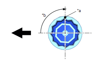
|
*a |
Paint Mark |
|
*b |
90° |

|
Front of Engine |
(j) Tighten the connecting rod bolts 90° as shown in the illustration.
NOTICE:
Do not turn the crankshaft during the measurement.
(k) Remove the 2 connecting rod bolts and connecting rod bearing cap.
HINT:
Keep the connecting rod bearing and connecting rod bearing cap together.
|
(l) Measure the Plastigage at its widest point. Standard Oil Clearance: 0.032 to 0.065 mm (0.00126 to 0.00256 in.) Maximum Oil Clearance: 0.065 mm (0.00256 in.) HINT:
Standard Connecting Rod Big End Inside Diameter:
Standard Connecting Rod Bearing Center Wall Thickness:
Standard Crank Pin Diameter: 47.992 to 48.000 mm (1.88945 to 1.88976 in.) NOTICE: Remove the Plastigage completely after the measurement. |
|
(m) Perform the inspection above for each cylinder.
5. REMOVE PISTON WITH CONNECTING ROD
(a) Using a ridge reamer, remove all the carbon from the top of each cylinder.
(b) Remove the 6 connecting rod bolts, 3 connecting rod bearing caps and 3 connecting rod bearings.
(c) Push the 3 pistons, 3 connecting rods and 3 connecting rod bearings out through the top of the cylinder block sub-assembly.
HINT:
- Keep the connecting rod bearings, connecting rods and connecting rod bearing caps together.
- Arrange the removed parts in such a way that they can be reinstalled to their original locations.
6. REMOVE CONNECTING ROD BEARING
(a) Remove the 6 connecting rod bearings from the 3 connecting rods and 3 connecting rod bearing caps.
HINT:
Arrange the removed parts in such a way that they can be reinstalled to their original locations.
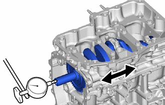
7. INSPECT CRANKSHAFT THRUST CLEARANCE
|
(a) Using a dial indicator, measure the crankshaft thrust clearance while prying the crankshaft back and forth with a screwdriver. Standard Thrust Clearance: 0.02 to 0.22 mm (0.000787 to 0.00866 in.) Maximum Thrust Clearance: 0.22 mm (0.00866 in.) HINT: If the thrust clearance is more than the maximum, replace the crankshaft thrust washers as a set. If necessary, replace the crankshaft. Standard Thrust Washer Thickness: 2.415 to 2.470 mm (0.0951 to 0.0972 in.) |
|
8. REMOVE CRANKSHAFT
|
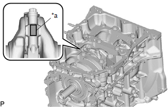
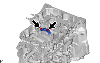
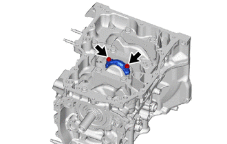
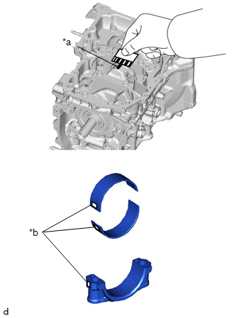
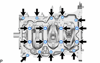
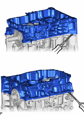
(a) Uniformly loosen and remove the 8 crankshaft bearing cap set bolts and 10 bolts. |
|
|
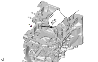
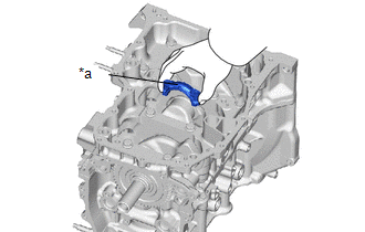
(b) Remove the crankshaft bearing cap from the cylinder block sub-assembly with a screwdriver with its tip wrapped with protective tape. HINT:
|
|
(c) Remove the crankshaft from the cylinder block sub-assembly.
HINT:
Keep the crankshaft bearings and crankshaft thrust washers together with the cylinder block sub-assembly.
(d) Check each crankshaft journal and crankshaft bearing for pitting and scratches.
HINT:
If the journal or crankshaft bearing is damaged, replace the crankshaft bearings. If necessary, replace the crankshaft.
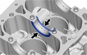
9. REMOVE CRANKSHAFT THRUST WASHER
|
(a) Remove the 2 crankshaft thrust washers from the No. 3 journal position of the cylinder block sub-assembly. |
|
10. REMOVE CRANKSHAFT BEARING
(a) Remove the 4 No. 1 crankshaft bearings and 4 No. 2 crankshaft bearings from the cylinder block sub-assembly and crankshaft bearing cap.
HINT:
Arrange the removed parts in such a way that they can be reinstalled to their original locations.
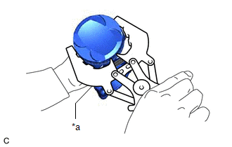
11. REMOVE PISTON RING SET
|
(a) Using a piston ring expander, remove the No. 1 compression ring and No. 2 compression ring from the piston. |
|
(b) Remove the oil ring expander, upper side rail and lower side rail from the piston by hand.
HINT:
Arrange the removed parts in such a way that they can be reinstalled to their original locations.
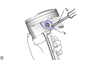
12. REMOVE PISTON PIN HOLE SNAP RING
|
(a) Using a screwdriver, pry out the 2 piston pin hole snap rings from the piston. HINT: Tape the screwdriver tip before use. |
|
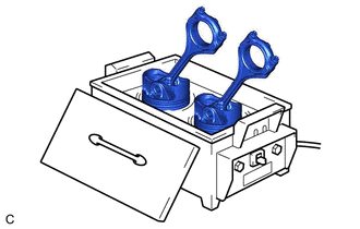
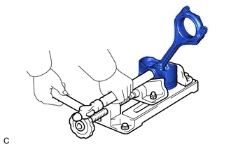
13. REMOVE PISTON
|
(a) Gradually heat each piston to between 80 and 90°C (176 and 194°F). CAUTION: Be sure to wear protective gloves. |
|
|
(b) Using a brass bar and a hammer, lightly tap out the piston pin and remove the connecting rod. HINT:
|
|
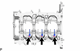
14. REMOVE NO. 1 OIL NOZZLE SUB-ASSEMBLY
|
(a) Using a 5 mm hexagon wrench, remove the 3 bolts and 3 No. 1 oil nozzle sub-assemblies from the cylinder block sub-assembly. |
|
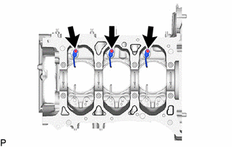
15. REMOVE NO. 2 OIL NOZZLE SUB-ASSEMBLY
|
(a) Using a 5 mm hexagon wrench, remove the 3 bolts and 3 No. 2 oil nozzle sub-assemblies from the cylinder block sub-assembly. |
|
16. REMOVE NO. 3 OIL NOZZLE SUB-ASSEMBLY
|
(a) Using a 5 mm hexagon wrench, remove the 3 bolts and 3 No. 3 oil nozzle sub-assemblies from the cylinder block sub-assembly. |
|
17. REMOVE STUD BOLT
NOTICE:
If a stud bolt is deformed or its threads are damaged, replace it.
(a) Using an E8 "TORX" socket wrench, remove the 7 stud bolts.

|
|
|
![2023 - 2025 MY GR Corolla [09/2022 - ]; G16E-GTS (ENGINE CONTROL): SFI SYSTEM: REGISTRATION](/t3Portal/stylegraphics/info.gif)
