| Last Modified: 07-31-2024 | 6.11:8.1.0 | Doc ID: RM10000000260TT |
| Model Year Start: 2023 | Model: GR Corolla | Prod Date Range: [09/2022 - ] |
| Title: G16E-GTS (ENGINE MECHANICAL): ENGINE UNIT: INSTALLATION; 2023 - 2025 MY GR Corolla [09/2022 - ] | ||
INSTALLATION
CAUTION / NOTICE / HINT
NOTICE:
This procedure includes the installation of small-head bolts. Refer to Small-Head Bolts of Basic Repair Hint to identify the small-head bolts.
Click here
![2019 - 2025 MY Corolla Corolla Hatchback Corolla HV GR Corolla [06/2018 - ]; INTRODUCTION: REPAIR INSTRUCTION: PRECAUTION](/t3Portal/stylegraphics/info.gif)
PROCEDURE
1. INSTALL NO. 3 CYLINDER BLOCK INSULATOR
(a) Install the No. 3 cylinder block insulator to the oil pan sub-assembly.
2. INSTALL INTAKE PIPE OR HOSE STAY
(a) Install the intake pipe or hose stay to the cylinder head cover sub-assembly with the 3 bolts.
Torque:
10 N·m {102 kgf·cm, 7 ft·lbf}
3. INSTALL FUEL HOSE BRACKET
(a) Install the fuel hose bracket to the cylinder head cover sub-assembly with the 2 bolts.
Torque:
10 N·m {102 kgf·cm, 7 ft·lbf}
4. INSTALL ENGINE COVER BRACKET
(a) Install the engine cover bracket to the No. 1 vacuum pump bracket with the bolt.
Torque:
21 N·m {214 kgf·cm, 15 ft·lbf}
5. INSTALL ENGINE COVER JOINT
(a) Install the 2 engine cover joints to the cylinder head cover sub-assembly.
Torque:
10 N·m {102 kgf·cm, 7 ft·lbf}
6. INSTALL IGNITION COIL ASSEMBLY
Click here
7. INSTALL VACUUM REGULATING VALVE ASSEMBLY
(a) Install the vacuum regulating valve assembly to the cylinder head cover sub-assembly with the 2 bolts.
Torque:
10 N·m {102 kgf·cm, 7 ft·lbf}
8. INSTALL VENTILATION HOSE
(a) Install the ventilation hose to the cylinder head cover sub-assembly and slide the clip to secure it.
(b) Engage the clamp.
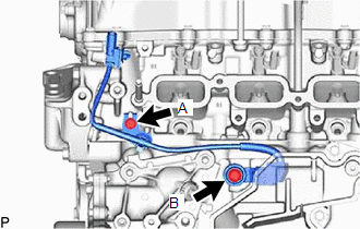
9. INSTALL SENSOR WIRE
|
(a) Install the sensor wire to the cylinder head sub-assembly and cylinder block sub-assembly with the 2 bolts. Torque: Bolt (A) : 10 N·m {102 kgf·cm, 7 ft·lbf} Bolt (B) : 21 N·m {214 kgf·cm, 15 ft·lbf} |
|
10. INSTALL NO. 2 CYLINDER BLOCK INSULATOR
(a) Install the No. 2 cylinder block insulator to the cylinder block sub-assembly.
11. INSTALL FUEL INJECTOR SEAL
Click here
12. INSTALL DIRECT FUEL INJECTOR ASSEMBLY
Click here
13. INSTALL NO. 6 ENGINE WIRE
Click here
14. INSTALL FUEL DELIVERY PIPE SUB-ASSEMBLY
Click here
15. INSTALL FUEL PUMP ASSEMBLY
Click here
16. INSTALL NO. 1 FUEL PIPE SUB-ASSEMBLY
Click here
17. INSTALL INJECTOR VIBRATION INSULATOR
Click here
18. INSTALL FUEL DELIVERY SPACER
Click here
19. INSTALL FUEL DELIVERY PIPE
Click here
20. INSTALL NO. 1 DELIVERY PIPE SPACER
(a) Install the 2 No. 1 delivery pipe spacers to the cylinder head sub-asembly.
21. INSTALL FUEL DELIVERY GUARD
Click here
22. INSTALL OIL LEVEL GAGE GUIDE
Click here
23. INSTALL OIL LEVEL GAGE SUB-ASSEMBLY
Click here
24. INSTALL FUEL TUBE SUB-ASSEMBLY
(a) Install the fuel tube sub-assembly.
Click here
(b) Install the bolt.
Torque:
10 N·m {102 kgf·cm, 7 ft·lbf}
(c) Install the fuel pipe clamp to the fuel tube connector.
25. INSTALL NO. 7 ENGINE WIRE
(a) Connect the 2 connectors and install the No. 7 engine wire.
(b) Engage the clamp.
26. INSTALL WATER BY-PASS PIPE
(a) Install the water by-pass pipe to the water inlet with thermostat sub-assembly and slide the clip to secure it.
(b) Install the bolt and nut.
Torque:
10 N·m {102 kgf·cm, 7 ft·lbf}
27. INSTALL NO. 1 INTAKE MANIFOLD TO HEAD GASKET
Click here
28. INSTALL NO. 1 VENTILATION FLANGE SEPARATOR
Click here
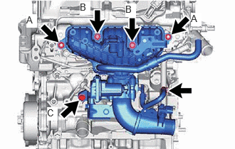
29. INSTALL INTAKE MANIFOLD
|
(a) Temporarily install the intake manifold with the 3 bolts and 2 nuts. |
|
|
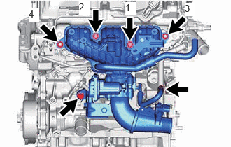
(b) Tighten the 2 bolts (B) and 2 nuts (A) in the order shown in the illustration. Torque: Nut (A), Bolt (B) : 21 N·m {214 kgf·cm, 15 ft·lbf} |
|
(c) Tighten the bolt (C).
Torque:
43 N·m {438 kgf·cm, 32 ft·lbf}
(d) Connect the No. 2 water by-pass hose to the water by-pass connector and slide the clip to secure it.
30. INSTALL NO. 2 ENGINE COVER BRACKET
(a) Install the No. 2 engine cover bracket to the intake manifold with the bolt.
Torque:
10 N·m {102 kgf·cm, 7 ft·lbf}
31. CONNECT NO. 6 ENGINE WIRE
(a) Engage the 5 clamps and connect the No. 6 engine wire.
32. INSTALL PURGE VALVE (PURGE VSV)
Click here
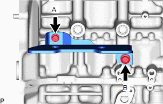
33. INSTALL NO. 2 TURBO INSULATOR
|
(a) Install the No. 2 turbo insulator to the cylinder block sub-assembly with the 2 bolts. Torque: Bolt (A) : 21 N·m {214 kgf·cm, 15 ft·lbf} Bolt (B) : 30 N·m {306 kgf·cm, 22 ft·lbf} |
|
34. INSTALL EXHAUST MANIFOLD TO HEAD GASKET
Click here
35. INSTALL TURBOCHARGER SUB-ASSEMBLY
(a) Install the collar with the red side facing the rear of the vehicle.
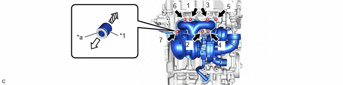
|
*1 |
COLLAR |
- |
- |
|
*a |
Red Side |
- |
- |

|
Rear Side |

|
Front Side |
(b) Install the turbocharger sub-assembly with 7 new nuts in the order shown in the illustration.
Torque:
44.3 N·m {452 kgf·cm, 33 ft·lbf}
|
(c) Connect the No. 1 turbo water pipe sub-assembly with the bolts. Torque: Bolt (A) : 13 N·m {133 kgf·cm, 10 ft·lbf} |
|
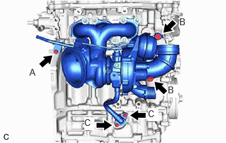
(d) Install the inlet turbo oil pipe union 2 bolts.
Torque:
Bolt (B) :
35 N·m {357 kgf·cm, 26 ft·lbf}
(e) Connect the outlet turbo oil pipe with the 2 bolts.
Torque:
Bolt (C) :
13 N·m {133 kgf·cm, 10 ft·lbf}
36. INSTALL NO. 1 TURBO INSULATOR
Click here
37. INSTALL NO. 4 CYLINDER BLOCK INSULATOR
(a) Install the No. 4 cylinder brock insulator with the 2 bolts.
Torque:
10 N·m {102 kgf·cm, 7 ft·lbf}
38. INSTALL DRIVE SHAFT BEARING BRACKET
(a) Install the drive shaft bearing bracket to the cylinder block sub-assembly with the 3 bolts.
Torque:
63.7 N·m {650 kgf·cm, 47 ft·lbf}
39. INSTALL ENGINE HANGER BRACKET
(a) Install the engine hanger bracket to the cylinder head sub-assembly with the 2 bolts.
Torque:
43 N·m {438 kgf·cm, 32 ft·lbf}
40. INSTALL INTAKE AIR PIPE
|
(a) Install the intake air pipe and tighten the hose clamp. Torque: 4.0 N·m {41 kgf·cm, 35 in·lbf} |
|
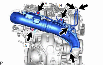
(b) Install the 3 bolts.
Torque:
Bolt (A) :
21 N·m {214 kgf·cm, 15 ft·lbf}
Bolt (B) :
10 N·m {102 kgf·cm, 7 ft·lbf}
(c) Connect the ventilation hose.
(d) Connect the No. 2 vacuum transmitting hose.
(e) Connect the No. 1 vacuum transmitting hose.
41. INSTALL VACUUM SENSOR ASSEMBLY
Click here
42. INSTALL E.F.I. VACUUM SENSOR ASSEMBLY (MANIFOLD ABSOLUTE PRESSURE SENSOR)
Click here
43. INSTALL WATER BY-PASS HOSE ASSEMBLY
(a) Install the water by-pass hose assembly and slide the 2 clip to secure it.
(b) Engage the clamp.
44. INSTALL NO. 4 WATER BY-PASS PIPE
|
(a) Install the No. 4 water by-pass pipe and slide the clip to secure it. |
|
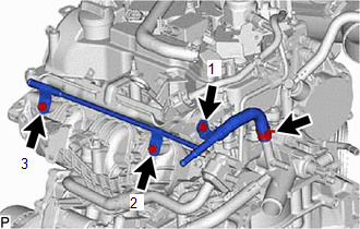
(b) Install the No. 4 water by-pass pipe with the 3 bolts in the order shown in the illustration.
Torque:
10 N·m {102 kgf·cm, 7 ft·lbf}
45. INSTALL NO. 3 WATER BY-PASS PIPE
(a) Install the No. 3 water by-pass pipe and slide the clip to secure it.
(b) Connect the No. 3 water by-pass pipe with the bolt.
Torque:
10 N·m {102 kgf·cm, 7 ft·lbf}
46. INSTALL NO. 1 WATER BY-PASS PIPE
(a) Install the No. 1 water by-pass pipe and slide the clip to secure it.
(b) Connect the No. 1 water by-pass pipe with the bolt and nut.
Torque:
10 N·m {102 kgf·cm, 7 ft·lbf}
47. INSTALL NO. 1 TURBO WATER HOSE
(a) Install the No. 1 turbo water hose and slide the 2 clips to secure it.
48. INSTALL NO. 3 VACUUM TRANSMITTING HOSE
(a) Install the No. 3 vacuum transmitting hose.
(b) Engage the 2 clamps.
49. INSTALL NO. 5 WATER BY-PASS HOSE
(a) Install the No. 5 water by-pass hose and slide the 2 clips to secure it.
(b) Install the bolt.
Torque:
10 N·m {102 kgf·cm, 7 ft·lbf}
50. INSTALL NO. 6 WATER BY-PASS HOSE
(a) Install the No. 6 water by-pass hose and slide the 2 clips to secure it.
(b) Engage the clamp.
51. INSTALL NO. 2 AIR HOSE
(a) Install the No. 2 air hose and tighten the hose clamp.
Torque:
6.0 N·m {61 kgf·cm, 53 in·lbf}
52. INSTALL FUEL TUBE SUB-ASSEMBLY
(a) Install the fuel tube sub-assembly to the fuel pipe sub-assembly.
Click here
(b) Engage the clamp.
53. INSTALL COMPRESSOR ASSEMBLY WITH PULLEY
Click here
|
|
|