| Last Modified: 05-13-2024 | 6.11:8.1.0 | Doc ID: RM10000000260TS |
| Model Year Start: 2023 | Model: GR Corolla | Prod Date Range: [09/2022 - ] |
| Title: G16E-GTS (ENGINE MECHANICAL): ENGINE UNIT: REASSEMBLY; 2023 - 2025 MY GR Corolla [09/2022 - ] | ||
REASSEMBLY
CAUTION / NOTICE / HINT
NOTICE:
This procedure includes the installation of small-head bolts. Refer to Small-Head Bolts of Basic Repair Hint to identify the small-head bolts.
Click here
![2019 - 2025 MY Corolla Corolla Hatchback Corolla HV GR Corolla [06/2018 - ]; INTRODUCTION: REPAIR INSTRUCTION: PRECAUTION](/t3Portal/stylegraphics/info.gif)
PROCEDURE
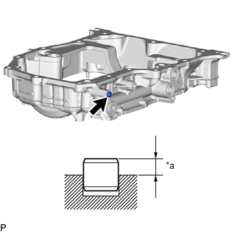
1. INSTALL RING PIN
NOTICE:
It is not necessary to remove the ring pins unless they are being replaced.
|
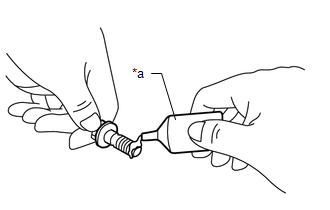
(a) Using a plastic hammer, tap in a new ring pin to the oil pan sub-assembly. Standard Protrusion Height: 3.0 to 5.0 mm (0.118 to 0.197 in.) |
|
|
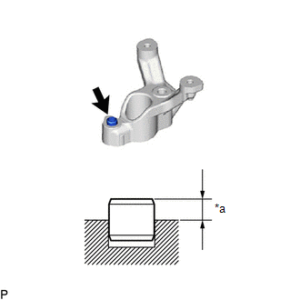
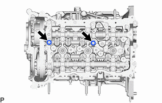
(b) Using a plastic hammer, tap in a new ring pin to the camshaft position sensor holder. Standard Protrusion Height: 3.5 to 4.5 mm (0.138 to 0.177 in.) |
|
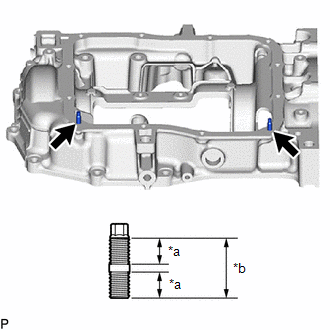
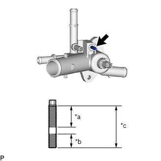
2. INSTALL STUD BOLT
NOTICE:
If a stud bolt is deformed or its threads are damaged, replace it.
|
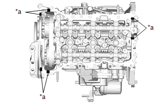
(a) Using an E6 "TORX" socket wrench, install the 2 stud bolts to the oil pan sub-assembly. Torque: 4.0 N·m {41 kgf·cm, 35 in·lbf} |
|
|
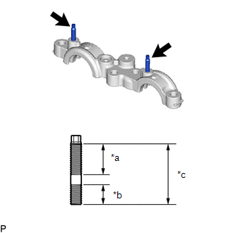
(b) Using an E6 "TORX" socket wrench, install the stud bolt to the No. 2 camshaft bearing cap. Torque: 4.0 N·m {41 kgf·cm, 35 in·lbf} |
|
|
(c) Using an E6 "TORX" socket wrench, install the stud bolt to the outlet water sub-assembly. Torque: 4.0 N·m {41 kgf·cm, 35 in·lbf} |
|
3. INSPECT BALANCESHAFT BACKLASH
Click here
4. INSTALL REAR ENGINE OIL SEAL
Click here
5. INSTALL BALANCESHAFT HOUSING SPACER
|
(a) Install the balanceshaft housing spacer to the crankshaft bearing cap. |
|
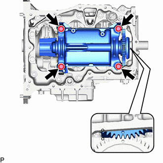
6. INSTALL ENGINE BALANCER ASSEMBLY
|
(a) Install a new o-ring to the crankshaft bearing cap. |
|
|
(b) Install the engine balancer assembly to the crankshaft bearing cap with the 4 bolts. Torque: 1st : 43 N·m {438 kgf·cm, 32 ft·lbf} 2nd : 54 N·m {551 kgf·cm, 40 ft·lbf} |
|
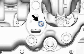
7. INSTALL OIL STRAINER SUB-ASSEMBLY
(a) Apply a light coat of engine oil to a new oil strainer gasket.
|
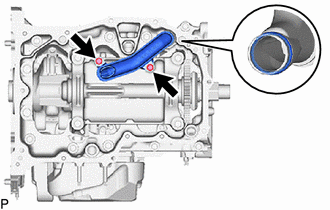
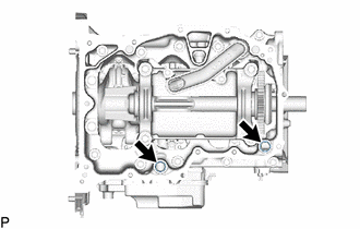
(b) Install the oil strainer sub-assembly and oil strainer gasket to the stiffening crankcase assembly with the 2 bolts. Torque: 10 N·m {102 kgf·cm, 7 ft·lbf} |
|
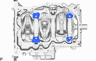
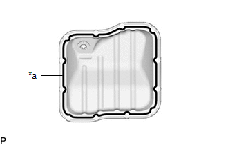
8. INSTALL OIL PAN SUB-ASSEMBLY
|
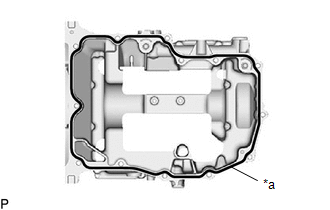
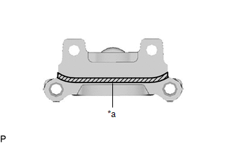
(a) Apply seal packing in a continuous line as shown in the illustration. Seal Packing: Toyota Genuine Seal Packing Black, Three Bond 1207B or equivalent Standard Seal Packing Dimension:
NOTICE:
|
|
|
(b) Install the 2 new o-ring to the crankshaft bearing cap. |
|
|
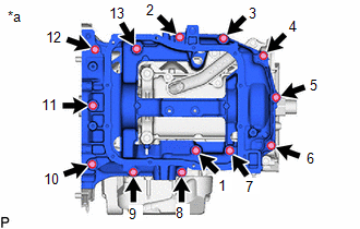
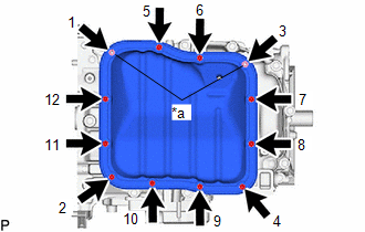
(c) Temporarily install the oil pan sub-assembly with the 13 bolts. Bolt Length :
|
|

|
(d) Tighten the 13 bolts in the order shown in the illustration to install the oil pan sub-assembly. Torque: 25 N·m {255 kgf·cm, 18 ft·lbf} |
|
9. INSTALL NO. 2 OIL PAN SUB-ASSEMBLY
|
(a) Apply seal packing in a continuous line as shown in the illustration. Seal Packing: Toyota Genuine Seal Packing Black, Three Bond 1207B or equivalent Standard Seal Packing Dimension: 2.5 to 3.5 mm (0.0984 to 0.138 in.) NOTICE:
|
|
|
(b) Install the No. 2 oil pan sub-assembly with the 10 bolts and 2 nuts in several steps in the order shown in the illustration. Torque: 10 N·m {102 kgf·cm, 7 ft·lbf} |
|
10. INSTALL OIL PAN DRAIN PLUG
(a) Install a new oil pan drain gasket and the No. 2 oil pan drain plug to the oil pan sub-assembly.
Torque:
40 N·m {408 kgf·cm, 30 ft·lbf}
11. INSTALL OIL FILTER BRACKET SUB-ASSEMBLY
(a) Install 2 new gaskets and the oil filter bracket sub-assembly to the oil pan sub-assembly.
Torque:
21 N·m {214 kgf·cm, 15 ft·lbf}
12. INSTALL OIL COOLER ASSEMBLY
Click here
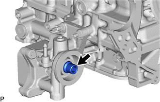
13. INSTALL OIL FILTER UNION
|
(a) Using a 12 mm hexagon socket wrench, install the oil filter union to the crank shaft bearing cap. Torque: 29.5 N·m {301 kgf·cm, 22 ft·lbf} |
|
14. INSTALL OIL FILTER SUB-ASSEMBLY
Click here
15. INSTALL CYLINDER HEAD GASKET
Click here
16. INSTALL CYLINDER HEAD SUB-ASSEMBLY
HINT:
The cylinder head set bolts are tightened in 3 progressive steps.
(a) Place the cylinder head sub-assembly on the cylinder block sub-assembly.
NOTICE:
- Ensure that the contact surface of the cylinder head sub-assembly is free of oil.
- Place the cylinder head sub-assembly on the cylinder block sub-assembly gently in order not to damage the cylinder head gasket with the bottom of the cylinder head sub-assembly.
(b) Install the 8 plate washers to the 8 cylinder head set bolts.
(c) Apply a light coat of engine oil to the threads and under the heads of the cylinder head set bolts.
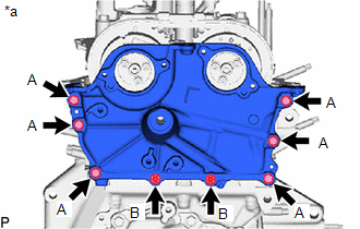
(d) Install the 8 cylinder head set bolts and 3 bolts to the cylinder head sub-assembly.

|
Front of Engine |
Bolt Diameter:
|
Item |
Diameter |
|---|---|
|
Bolt (A) |
11 mm (0.433 in.) |
|
Bolt (B) |
12 mm (0.472 in.) |
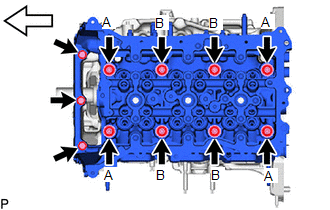
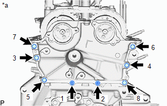
(e) Step 1:
(1) Using a 12 mm socket wrench, install and uniformly tighten the 8 cylinder head set bolts in several steps in the order shown in the illustration.
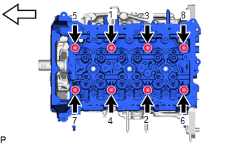
|
|
Front of Engine |
NOTICE:
Be careful not to drop the plate washers into the cylinder head sub-assembly.
Torque:
Bolt (A) :
40 N·m {408 kgf·cm, 30 ft·lbf}
Bolt (B) :
50 N·m {510 kgf·cm, 37 ft·lbf}
(f) Step 2:
(1) Mark each cylinder head set bolt head with paint as shown in the illustration.
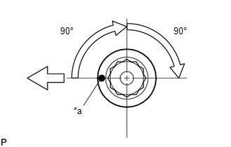
|
*a |
Paint Mark |
|
|
Front of Engine |
(2) Tighten the cylinder head set bolts 90° in the order shown in step 1.
(g) Step 3:
(1) Tighten the cylinder head set bolts another 90° in the order shown in step 1.
(2) Check that the paint marks are now facing rearward.
HINT:
Perform inspection after repair after replacing the cylinder head sub-assembly.
Click here
|
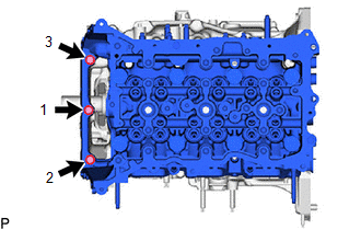
(h) Install the 3 bolts in the order shown in the illustration. Torque: 25 N·m {255 kgf·cm, 18 ft·lbf} |
|
17. INSTALL VALVE STEM CAP
(a) Apply a light coat of engine oil to the valve stem cap ends.
|
(b) Install the 12 valve stem caps to the cylinder head sub-assembly. NOTICE:
|
|
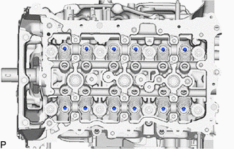
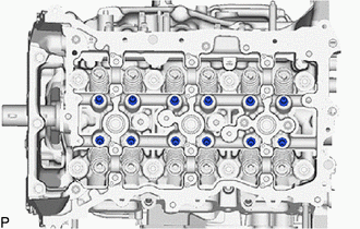
18. INSTALL VALVE LASH ADJUSTER ASSEMBLY
(a) Inspect the 12 valve lash adjuster assemblies before installing them.
Click here
(b) Install the 12 valve lash adjuster assemblies to the cylinder head sub-assembly.
NOTICE:
Install the same parts in the same combination to their original locations.
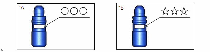
|
*A |
for intake side |
*B |
for exhaust side |
19. INSTALL NO. 1 VALVE ROCKER ARM SUB-ASSEMBLY
|
(a) Apply engine oil to the valve lash adjuster assembly tips and valve stem caps. |
|
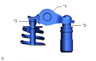
(b) Install the 12 No. 1 valve rocker arm sub-assemblies as shown in the illustration.
NOTICE:
Install the same parts in the same combination to their original locations.
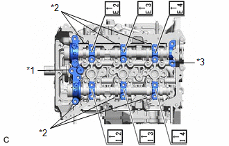
20. INSTALL NO. 1 CAMSHAFT BEARING CAP
(a) Install the No. 1 camshaft bearing cap to the cylinder head sub-assembly.
21. INSTALL NO. 5 CAMSHAFT BEARING CAP
(a) Install the No. 5 camshaft bearing cap to the cylinder head sub-assembly.
22. INSTALL EXHAUST CAMSHAFT SUB-ASSEMBLY
HINT:
Perform inspection after repair after replacing the exhaust camshaft sub-assembly.
Click here
(a) Clean the camshaft journals and cylinder head sub-assembly.
(b) Apply a light coat of engine oil to the camshaft journals and cylinder head sub-assembly.
(c) Install the exhaust camshaft sub-assembly to the cylinder head sub-assembly.
23. INSTALL INTAKE CAMSHAFT SUB-ASSEMBLY
HINT:
Perform inspection after repair after replacing the intake camshaft sub-assembly.
Click here
(a) Clean the camshaft journals and cylinder head sub-assembly.
(b) Apply a light coat of engine oil to the camshaft journals, cylinder head sub-assembly.
(c) Install the intake camshaft sub-assembly to the cylinder head sub-assembly.
24. INSTALL CAMSHAFT BEARING CAP
|
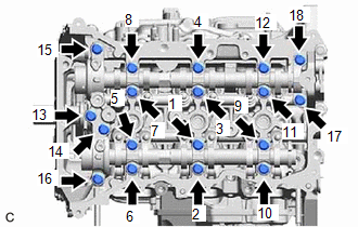
(a) Set the No. 2 camshaft bearing cap, 6 No. 4 camshaft bearing caps and No. 6 camshaft bearing cap. Installation Position of Camshaft Bearing Cap:
|
|
|
(b) Temporarily install and uniformly tighten the 18 bolts. Torque: 8.0 N·m {82 kgf·cm, 71 in·lbf} Bolt Length:
|
|

|
(c) Tighten the 18 bolts in the order shown in the illustration. Torque: 18 N·m {184 kgf·cm, 13 ft·lbf} |
|
25. TEMPORARILY TIGHTEN CAMSHAFT POSITION SENSOR HOLDER
(a) Temporarily tighten the camshaft position sensor holder with the bolt.
26. INSTALL FUEL PUMP LIFTER HOUSING
|
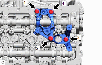
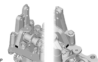
(a) Install the fuel pump lifter housing with the 4 bolts in the order shown in the illustration. Torque: 21 N·m {214 kgf·cm, 15 ft·lbf} |
|
27. INSTALL FUEL PUMP LIFTER GUIDE
(a) Install the fuel pump lifter guide with the 2 bolts.
Torque:
10 N·m {102 kgf·cm, 7 ft·lbf}
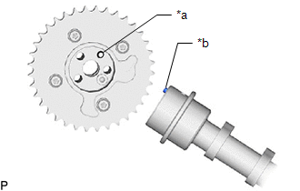
28. INSTALL CAMSHAFT TIMING GEAR ASSEMBLY
HINT:
Perform inspection after repair after replacing the camshaft timing gear assembly.
Click here
|
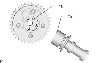
(a) Align and fit the knock pin of the intake camshaft sub-assembly to the knock pin hole of the camshaft timing gear assembly. |
|
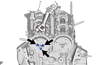
|
(b) Using a wrench, hold the hexagonal portion of the intake camshaft sub-assembly. NOTICE:
|
|
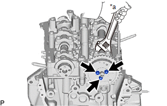
(c) Using a 5 mm hexagon socket wrench, install the camshaft timing gear assembly and the camshaft timing valve assembly with the 3 bolts.
Torque:
19 N·m {194 kgf·cm, 14 ft·lbf}
29. INSTALL CAMSHAFT TIMING EXHAUST GEAR ASSEMBLY
HINT:
Perform inspection after repair after replacing the camshaft timing exhaust gear assembly.
Click here
|
(a) Align and fit the knock pin of the exhaust camshaft sub-assembly to the knock pin hole of the camshaft timing exhaust gear assembly. |
|
(b) Using a wrench, hold the hexagonal portion of the exhaust camshaft sub-assembly.
NOTICE:
- Be careful not to damage the cylinder head sub-assembly or spark plug tube with the wrench.
- Do not disassemble the camshaft timing exhaust gear assembly.
|
(c) Using a 5 mm hexagon socket wrench, install the camshaft timing gear assembly and the camshaft timing valve assembly with the 3 bolts. Torque: 19 N·m {194 kgf·cm, 14 ft·lbf} |
|
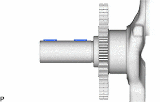
30. INSTALL CRANKSHAFT TIMING GEAR KEY
|
(a) Using a plastic hammer, tap in the 2 crankshaft timing gear keys. HINT: Tap in the crankshaft timing gear keys until they contact the crankshaft as shown in the illustration. |
|
31. INSTALL CRANKSHAFT TIMING GEAR OR SPROCKET
(a) Install the crankshaft timing gear or sprocket to the crankshaft.
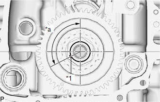
32. SET VALVE TIMING
(a) Temporarily install the crankshaft pulley bolt.
|
(b) Rotate the crankshaft 117.11° counterclockwise to position the crankshaft timing gear key as shown in the illustration. |
|
|
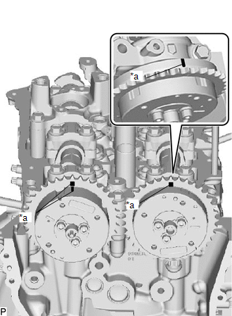
(c) Check that the timing marks of the camshaft timing exhaust gear assembly and camshaft timing gear assembly are as shown in the illustration. |
|
33. INSTALL NO. 1 CHAIN VIBRATION DAMPER
(a) Install the No. 1 chain vibration damper with the 2 bolts.
Torque:
21 N·m {214 kgf·cm, 15 ft·lbf}
34. INSTALL CHAIN SUB-ASSEMBLY
(a) Remove the crankshaft pulley bolt.
|
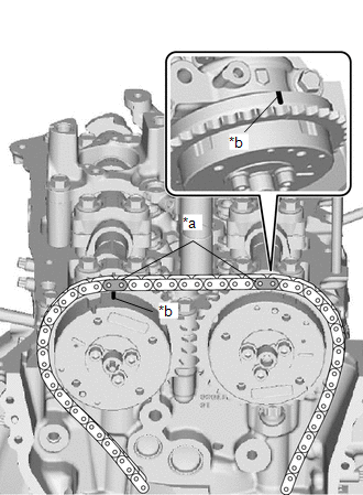
(b) Align the paint marks (pink) of the chain sub-assembly with the timing marks of the canshaft ttiming gear assembly, camshaft timing exhaust gear assembly and install the chain sub-assembly to the camshaft timing gear assembly and camshaft timing exhaust gear assembly. |
|
|
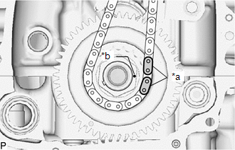
(c) Align the paint marks (yellow) of the chain sub-assembly with the timing mark of the crankshaft timing gear or sprocket and install the chain sub-assembly to the crankshaft timing gear or sprocket. |
|
35. INSTALL CHAIN TENSIONER SLIPPER
(a) Install the chain tensioner slipper with the bolt.
Torque:
21 N·m {214 kgf·cm, 15 ft·lbf}
36. INSTALL DAMPER PLATE SPACER
(a) Install the 2 damper plate spacers to the No. 2 camshaft bearing cap.
37. INSTALL TIMING CHAIN GUIDE
(a) Install the timing chain guide with the 2 nuts.
Torque:
10 N·m {102 kgf·cm, 7 ft·lbf}
38. INSTALL NO. 1 CHAIN TENSIONER ASSEMBLY
HINT:
After replacing or removing and installing the No. 1 chain tensioner assembly, an abnormal noise may occur at start up until the oil in the line has had time to replenish.
(a) Install the No. 1 chain tensioner assembly with the 2 bolts.
Torque:
10 N·m {102 kgf·cm, 7 ft·lbf}
(b) Remove the pin.
39. SET NO. 1 CYLINDER TO TDC (COMPRESSION)
Click here
40. INSTALL TIMING CHAIN COVER ASSEMBLY
Click here
41. INSTALL TIMING CHAIN COVER OIL SEAL
Click here
42. INSTALL NO. 2 TIMING CHAIN COVER ASSEMBLY
|
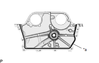
(a) Apply seal packing in a continuous line as shown in the illustration. Seal Packing: Toyota Genuine Seal Packing Black, Three Bond 1207B or equivalent Standard Seal Packing Dimension:
NOTICE:
|
|
|
(b) Apply adhesive to 2 or 3 threads at the end of each of the 2 bolts (B). Adhesive: Toyota Genuine Adhesive 1324, Three Bond 1324 or equivalent |
|
|
(c) Temporarily tighten the No. 2 timing chain cover assembly with the 8 bolts. |
|
|
(d) Tighten the 8 bolts in the order shown in the illustration. Torque: 12 N·m {122 kgf·cm, 9 ft·lbf} |
|
|
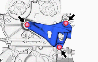
(e) Install the engine mounting bracket RH with the 3 bolts in the order shown in the illustration. Torque: 43 N·m {438 kgf·cm, 32 ft·lbf} NOTICE: After applying seal packing to the No. 2 timing chain cover assembly, install the engine mounting bracket RH within 10 minutes. |
|
43. INSTALL NO. 1 VACUUM PUMP BRACKET
|
(a) Apply seal packing in a continuous line as shown in the illustration. Seal Packing: Toyota Genuine Seal Packing Black, Three Bond 1207B or equivalent Standard Seal Packing Dimension:
NOTICE:
|
|
(b) Install the No. 1 vacuum pump bracket with the 2 bolts.
Torque:
21 N·m {214 kgf·cm, 15 ft·lbf}
|
(c) Wipe off any excess seal packing. |
|
44. INSTALL SPARK PLUG TUBE GASKET
(a) Install 3 new spark plug tube gaskets to the cylinder head cover sub-assembly.
45. INSTALL CYLINDER HEAD COVER SUB-ASSEMBLY
|
(a) Install 2 new camshaft bearing cap oil hole gaskets to the No. 2 camshaft bearing cap and fuel pump lifter housing. NOTICE: Remove any oil from the contact surfaces. |
|
(b) Install 5 new cylinder head cover gaskets to the cylinder head cover sub-assembly.
NOTICE:
Remove any oil from the contact surfaces.
(c) Apply seal packing as shown in the illustration.
|
*a |
Seal Packing Diameter: 3.0 to 6.0 mm (0.118 to 0.236 in.) |

|
Seal Packing |
Seal Packing:
Toyota Genuine Seal Packing Black, Three Bond 1207B or equivalent
Standard Seal Packing Diameter:
3.0 to 6.0 mm (0.118 to 0.236 in.)
NOTICE:
- Remove any oil from the contact surfaces.
- Install the cylinder head cover sub-assembly within 3 minutes and tighten the bolts within 15 minutes of applying seal packing.
- Do not start the engine for at least 2 hours after installation.
|
(d) Apply adhesive to 2 or 3 threads at the end of each of the bolt (D). Adhesive: Toyota Genuine Adhesive 1324, Three Bond 1324 or equivalent |
|
|
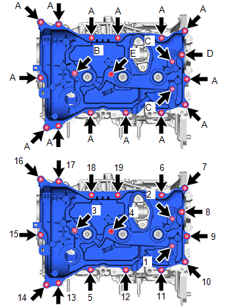
(e) Install the 2 camshaft position sensors (for exhaust side and for intake side) and cylinder head cover sub-assembly with the 19 bolts (A,B,C,D,E) in the order shown in the illustration. Bolt Length:
Torque: 10 N·m {102 kgf·cm, 7 ft·lbf} NOTICE:
|
|
46. INSTALL OUTLET WATER SUB-ASSEMBLY
(a) Install the outlet water sub-assembly and a new outlet water gasket to the cylinder head sub-assembly with the 2 nuts.
Torque:
21 N·m {214 kgf·cm, 15 ft·lbf}
47. INSTALL CRANKSHAFT PULLEY ASSEMBLY
|
(a) Align the crankshaft timing gear key with the key groove of the crankshaft pulley assembly. |
|
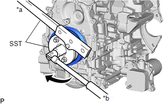
(b) Using SST, hold the crankshaft pulley assembly and install the a new crankshaft pulley set bolt.
SST: 09213-54015
SST: 09330-00021
Torque:
260 N·m {2651 kgf·cm, 192 ft·lbf}
(c) Mark each crankshaft pulley set bolt with paint as shown in the illustration.
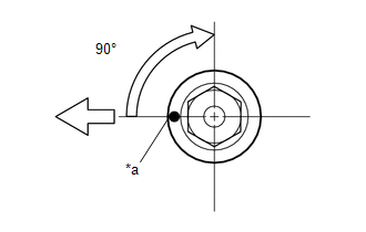
|
*a |
Paint Mark |
|
|
Front of Engine |
(d) Tighten the crankshaft pulley set bolt 90°.
48. INSTALL VACUUM PUMP ASSEMBLY
Click here
49. INSTALL PCV VALVE (VENTILATION VALVE SUB-ASSEMBLY)
Click here
50. INSTALL CRANK POSITION SENSOR
Click here
51. INSTALL OIL FILLER CAP GASKET
(a) Install a new oil filler cap gasket to the oil filler cap assembly.
52. INSTALL OIL FILLER CAP ASSEMBLY
(a) Install the oil filler cap sub-assembly to the cylinder head cover sub-assembly.
53. INSTALL WATER INLET WITH WATER PUMP HOUSING SUB-ASSEMBLY
Click here
54. INSTALL WATER INLET WITH THERMOSTAT SUB-ASSEMBLY
Click here
55. INSTALL CAM TIMING OIL CONTROL SOLENOID ASSEMBLY (for Intake Side)
Click here
56. INSTALL CAM TIMING OIL CONTROL SOLENOID ASSEMBLY (for Exhaust Side)
Click here
57. INSTALL OIL PRESSURE AND TEMPERATURE SENSOR
Click here
58. INSTALL SPARK PLUG
Click here
|
|
|