| Last Modified: 05-13-2024 | 6.11:8.1.0 | Doc ID: RM10000000260TR |
| Model Year Start: 2023 | Model: GR Corolla | Prod Date Range: [09/2022 - ] |
| Title: G16E-GTS (ENGINE MECHANICAL): ENGINE UNIT: DISASSEMBLY; 2023 - 2025 MY GR Corolla [09/2022 - ] | ||
DISASSEMBLY
CAUTION / NOTICE / HINT
NOTICE:
This procedure includes the removal of small-head bolts. Refer to Small-Head Bolts of Basic Repair Hint to identify the small-head bolts.
Click here
![2019 - 2025 MY Corolla Corolla Hatchback Corolla HV GR Corolla [06/2018 - ]; INTRODUCTION: REPAIR INSTRUCTION: PRECAUTION](/t3Portal/stylegraphics/info.gif)
PROCEDURE
1. REMOVE SPARK PLUG
Click here
2. REMOVE OIL PRESSURE AND TEMPERATURE SENSOR
Click here
3. REMOVE CAMSHAFT POSITION SENSOR (for Intake Side)
Click here
4. REMOVE CAMSHAFT POSITION SENSOR (for Exhaust Side)
Click here
5. REMOVE CAM TIMING OIL CONTROL SOLENOID ASSEMBLY (for Intake Side)
Click here
6. REMOVE CAM TIMING OIL CONTROL SOLENOID ASSEMBLY (for Exhaust Side)
Click here
7. REMOVE WATER INLET WITH THERMOSTAT SUB-ASSEMBLY
Click here
8. REMOVE WATER INLET WITH WATER PUMP HOUSING SUB-ASSEMBLY
Click here
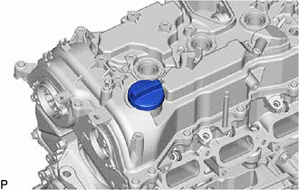
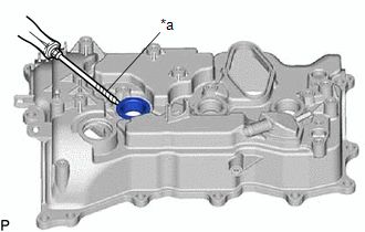
9. REMOVE OIL FILLER CAP ASSEMBLY
|
(a) Remove the oil filler cap assembly from the cylinder head cover sub-assembly. |
|
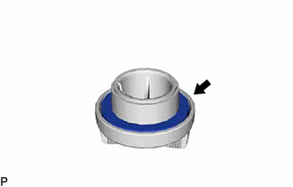
10. REMOVE OIL FILLER CAP GASKET
|
(a) Remove the oil filler cap gasket from the oil filler cap assembly. |
|
11. REMOVE CRANKSHAFT POSITION SENSOR
Click here
12. REMOVE PCV VALVE (VENTILATION VALVE SUB-ASSEMBLY)
Click here
13. REMOVE VACUUM PUMP ASSEMBLY
Click here
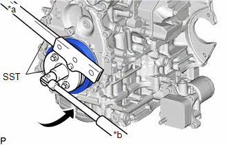
14. REMOVE CRANKSHAFT PULLEY ASSEMBLY
|
(a) Using SST, hold the crankshaft pulley assembly and loosen the crankshaft pulley set bolt. Further loosen the crankshaft pulley set bolt until 2 or 3 threads remain screwed into the crankshaft. SST: 09213-54015 SST: 09330-00021 |
|
|
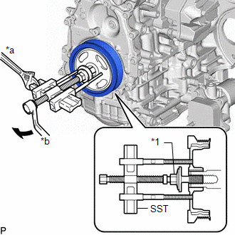
(b) Using SST and the crankshaft pulley set bolt, remove the crankshaft pulley assembly and crankshaft pulley set bolt. SST: 09950-50013 09951-05010 09952-05010 09953-05020 09954-05070 09957-04010 HINT: Apply lubricant to the threads and end of SST. |
|
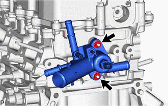
15. REMOVE OUTLET WATER SUB-ASSEMBLY
|
(a) Remove the 2 nuts, outlet water sub-assembly and outlet water gasket from the cylinder head sub-assembly. |
|
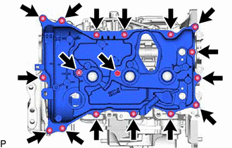
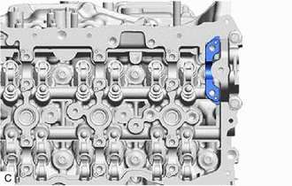
16. REMOVE CYLINDER HEAD COVER SUB-ASSEMBLY
|
(a) Remove the 17 bolts and cylinder head cover sub-assembly from the cylinder head sub-assembly. |
|
|
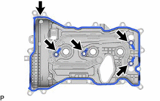
(b) Remove the 5 cylinder head cover gaskets from the cylinder head cover sub-assembly. |
|
|
(c) Remove the 2 camshaft bearing cap oil hole gaskets from the No. 1 camshaft bearing cap and fuel pump lifter housing. |
|
17. REMOVE SPARK PLUG TUBE GASKET
|
(a) Using a screwdriver, pry out the 3 spark plug tube gaskets from the cylinder head cover sub-assembly. NOTICE: Be careful not to damage the cylinder head cover sub-assembly. HINT: Tape the screwdriver tip before use. |
|
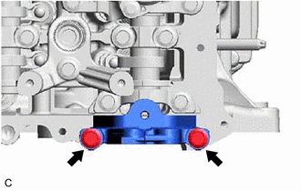
18. REMOVE NO. 1 VACUUM PUMP BRACKET
|
(a) Remove the 2 bolts and No. 1 vacuum pump bracket from the cylinder head sub-assembly. |
|
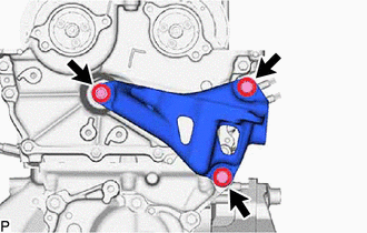
19. REMOVE ENGINE MOUNTING BRACKET RH
|
(a) Remove the 3 bolts and engine mounting bracket RH from the No. 2 timing chain cover assembly. |
|
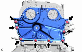
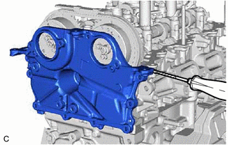
20. REMOVE NO. 2 TIMING CHAIN COVER ASSEMBLY
|
(a) Remove the 8 bolts. |
|
|
(b) Remove the No. 2 timing chain cover assembly from the cylinder head sub-assembly by prying the No. 2 timing chain cover assembly with a screwdriver with its tip wrapped with protective tape. |
|
21. REMOVE TIMING CHAIN COVER OIL SEAL
Click here
22. REMOVE TIMING CHAIN COVER ASSEMBLY
Click here
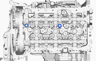
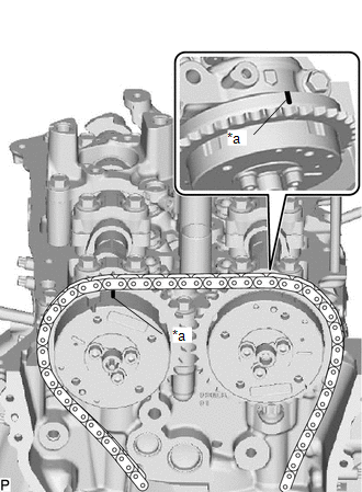
23. SET VALVE TIMING
(a) Temporarily install the crankshaft pulley bolt.
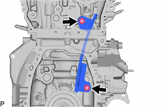
|
(b) Rotate the crankshaft clockwise and make sure that the timing marks of the camshaft timing gear assembly and camshaft timing exhaust gear assembly is at the top. |
|
|
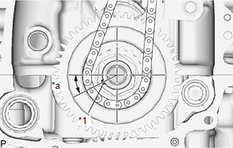
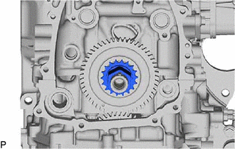
(c) Check that the crankshaft timing gear key as shown in the illustration. |
|
(d) Remove the crankshaft pulley bolt.
HINT:
As the exhaust camshaft sub-assembly may rotate counterclockwise strongly when the crankshaft pulley set bolt is removed, use a wrench to hold the hexagonal portion of the exhaust camshaft sub-assembly.
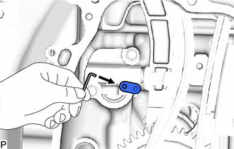
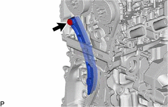
24. REMOVE NO. 1 CHAIN TENSIONER ASSEMBLY
|
(a) Turn the stopper plate of the No. 1 chain tensioner assembly clockwise to release the lock and push in the plunger. |
|
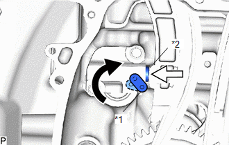
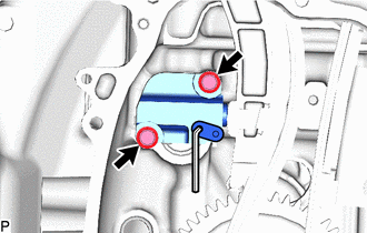
(b) Turn the stopper plate counterclockwise to set the lock.
|
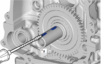
(c) Insert a pin into the stopper plate hole. |
|
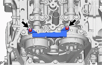
|
(d) Remove the 2 bolts and No. 1 chain tensioner assembly from the cylinder block sub-assembly. |
|
|
(e) Remove the chain tensioner gasket from the No. 1 chain tensioner assembly. |
|

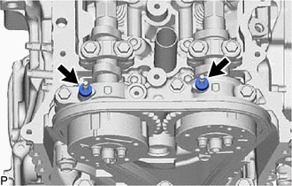
25. REMOVE TIMING CHAIN GUIDE
|
(a) Remove the 2 nut and timing chain guide from the damper plate spacer. |
|
26. REMOVE DAMPER PLATE SPACER
|
(a) Remove the damper plate spacers from the No. 2 camshaft bearing cap. |
|
27. REMOVE CHAIN TENSIONER SLIPPER
|
(a) Remove the bolt and chain tensioner slipper from the cylinder head sub-assembly. |
|
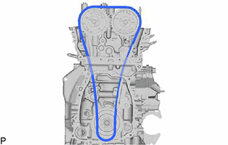
28. REMOVE CHAIN SUB-ASSEMBLY
|
(a) Remove the chain sub-assembly. |
|
29. REMOVE NO. 1 CHAIN VIBRATION DAMPER
|
(a) Remove the 2 bolts and No. 1 chain vibration damper. |
|
30. REMOVE CRANKSHAFT TIMING GEAR OR SPROCKET
|
(a) Remove the crankshaft timing gear or sprocket from the crankshaft. |
|
31. REMOVE CRANKSHAFT TIMING GEAR KEY
|
(a) Using a screwdriver, remove the 2 crankshaft timing gear keys from the crankshaft. HINT: Tape the screwdriver tip before use. |
|
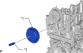
32. REMOVE CAMSHAFT TIMING EXHAUST GEAR ASSEMBLY
|
(a) Using a wrench, hold the hexagonal portion of the exhaust camshaft sub-assembly. NOTICE: Be careful not to damage the cylinder head sub-assembly or spark plug tube with the wrench. |
|
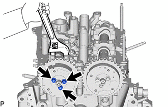
(b) Using a 5 mm hexagon socket wrench, remove the 3 bolts.
|
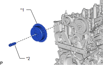
(c) Remove the camshaft timing exhaust gear assembly and camshaft timing valve assembly from the exhaust camshaft sub-assembly. |
|
33. REMOVE CAMSHAFT TIMING GEAR ASSEMBLY
|
(a) Using a wrench, hold the hexagonal portion of the intake camshaft sub-assembly. NOTICE: Be careful not to damage the cylinder head sub-assembly or spark plug tube with the wrench. |
|
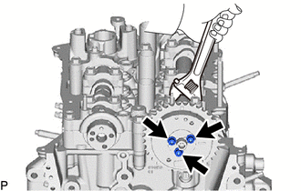
(b) Using a 5 mm hexagon socket wrench, remove the 3 bolts.
|
(c) Remove the camshaft timing gear assembly and camshaft timing valve assembly from the intake camshaft sub-assembly. |
|
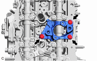
34. REMOVE FUEL PUMP LIFTER GUIDE
|
(a) Remove the 2 bolts and fuel pump lifter guide from the fuel pump lifter housing. |
|
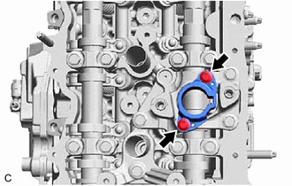
35. REMOVE FUEL PUMP LIFTER HOUSING
|
(a) Remove the 3 bolts and fuel pump lifter housing from the cylinder head sub-assembly. |
|
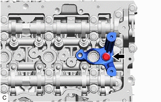
36. REMOVE CAMSHAFT POSITION SENSOR HOLDER
|
(a) Remove the bolt and camshaft position sensor holder from the cylinder head sub-assembly. |
|
37. REMOVE CAMSHAFT BEARING CAP
|
(a) Remove the 18 bolts. |
|
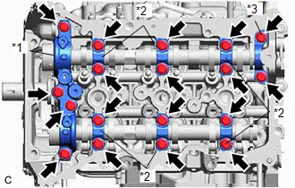
(b) Remove the No. 2 camshaft bearing cap, 6 No. 4 camshaft bearing caps and No. 6 camshaft bearing cap from the No. 1 camshaft bearing cap, camshaft bearing cap and No. 5 camshaft bearing cap.
HINT:
Arrange the removed parts in such a way that they can be reinstalled to their original locations.
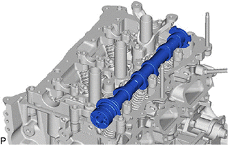
38. REMOVE EXHAUST CAMSHAFT SUB-ASSEMBLY
|
(a) Remove the exhaust camshaft sub-assembly from the cylinder head sub-assembly. |
|
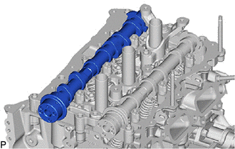
39. REMOVE INTAKE CAMSHAFT SUB-ASSEMBLY
|
(a) Remove the intake camshaft sub-assembly from the cylinder head sub-assembly. |
|
40. REMOVE NO. 1 CAMSHAFT BEARING CAP
|
(a) Remove the No. 1 camshaft bearing cap from the cylinder head sub-assembly. |
|
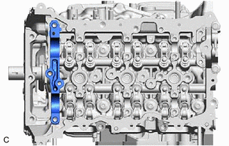
41. REMOVE NO. 5 CAMSHAFT BEARING CAP
|
(a) Remove the No. 5 camshaft bearing cap from the cylinder head sub-assembly. |
|
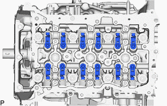
42. REMOVE NO. 1 VALVE ROCKER ARM SUB-ASSEMBLY
|
(a) Remove the 12 No. 1 valve rocker arm sub-assemblies from the cylinder head sub-assembly. HINT: Arrange the removed parts in such a way that they can be reinstalled to their original locations. |
|
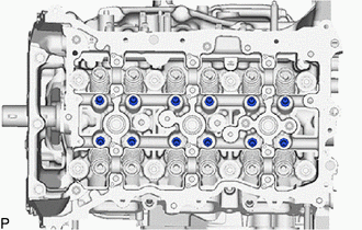
43. REMOVE VALVE LASH ADJUSTER ASSEMBLY
|
(a) Remove the 12 valve lash adjuster assemblies from the cylinder head sub-assembly. HINT: Arrange the removed parts in such a way that they can be reinstalled to their original locations. |
|
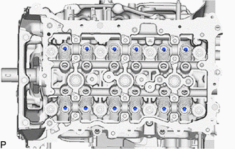
44. REMOVE VALVE STEM CAP
|
(a) Remove the 12 valve stem caps from the cylinder head sub-assembly. HINT: Arrange the removed parts in such a way that they can be reinstalled to their original locations. |
|
45. REMOVE CYLINDER HEAD SUB-ASSEMBLY
|
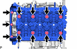
(a) Using a 12 mm socket wrench, uniformly loosen the 8 cylinder head set bolts in the order shown in the illustration. Remove the 8 cylinder head set bolts and 8 plate washers. NOTICE:
HINT: Arrange the removed parts in such a way that they can be reinstalled to their original locations. |
|
(b) Remove the 3 bolts and cylinder head sub-assembly from the cylinder block sub-assembly.
46. REMOVE CYLINDER HEAD GASKET
Click here
47. REMOVE OIL FILTER SUB-ASSEMBLY
Click here
48. REMOVE OIL FILTER UNION
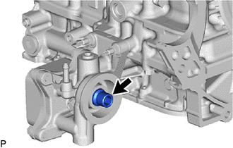
(a) Using a 12 mm hexagon socket wrench, remove the oil filter union from the oil filter bracket sub-assembly.
49. REMOVE OIL COOLER ASSEMBLY
Click here
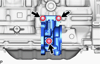
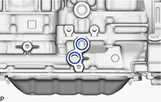
50. REMOVE OIL FILTER BRACKET SUB-ASSEMBLY
|
(a) Remove the 3 bolts and oil filter bracket sub-assembly from the cylinder block sub-assembly. |
|
|
(b) Remove the 2 gaskets. |
|
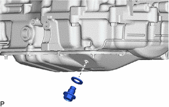
51. REMOVE OIL PAN DRAIN PLUG
|
(a) Remove the oil pan drain plug and oil pan drain gasket from the No. 2 oil pan sub-assembly. |
|
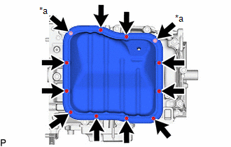
52. REMOVE NO. 2 OIL PAN SUB-ASSEMBLY
|
(a) Remove the 10 bolts and 2 nuts. |
|
|
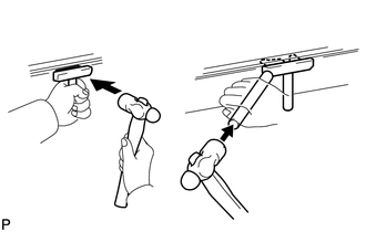
(b) Insert the blade of an oil pan seal cutter between the oil pan sub-assembly and stiffening crankcase assembly, cut through the applied sealer and remove the oil pan sub-assembly. NOTICE:
|
|
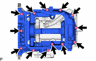
53. REMOVE OIL PAN SUB-ASSEMBLY
|
(a) Remove the 13 bolts and oil pan sub-assembly from the crankshaft bearing cap. |
|
54. REMOVE OIL STRAINER SUB-ASSEMBLY
|
(a) Remove the 2 bolts, oil strainer sub-assembly and oil strainer gasket from the crankshaft bearing cap. |
|
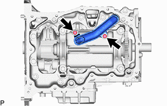
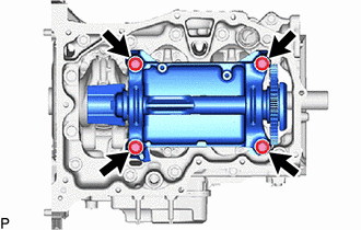
55. REMOVE ENGINE BALANCER ASSEMBLY
|
(a) Remove the 4 bolts and engine balancer assembly from the cylinder block sub-assembly. |
|
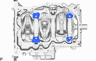
56. REMOVE BALANCESHAFT HOUSING SPACER
|
(a) Remove the 4 balanceshaft housing spacers from the cylinder block sub-assembly. |
|
57. REMOVE REAR ENGINE OIL SEAL
Click here
58. REMOVE STUD BOLT
NOTICE:
If a stud bolt is deformed or its threads are damaged, replace it.
59. REMOVE RING PIN
NOTICE:
It is not necessary to remove the ring pins unless they are being replaced.
|
|
|