| Last Modified: 01-27-2025 | 6.11:8.1.0 | Doc ID: RM10000000260SE |
| Model Year Start: 2023 | Model: GR Corolla | Prod Date Range: [09/2022 - ] |
| Title: BRAKE CONTROL / DYNAMIC CONTROL SYSTEMS: ELECTRONICALLY CONTROLLED BRAKE SYSTEM (for Gasoline Model without Electric Parking Brake System TMC Made): P057111; Brake Switch "A" Circuit Short to Ground; 2023 - 2025 MY Corolla Corolla Hatchback GR Corolla [09/2022 - ] | ||
|
DTC |
P057111 |
Brake Switch "A" Circuit Short to Ground |
DESCRIPTION
The skid control ECU (brake actuator assembly) inputs the stop light signal and brake operation condition.
When the brake pedal is depressed and the stop light switch signal is not input, this DTC is output.
|
DTC No. |
Detection Item |
DTC Detection Condition |
Trouble Area |
|---|---|---|---|
|
P057111 |
Brake Switch "A" Circuit Short to Ground |
Either of the following is detected:
|
|
WIRING DIAGRAM
Refer to DTC C13807E.
Click here
![2023 - 2025 MY Corolla Corolla Hatchback GR Corolla [09/2022 - ]; BRAKE CONTROL / DYNAMIC CONTROL SYSTEMS: ELECTRONICALLY CONTROLLED BRAKE SYSTEM (for Gasoline Model without Electric Parking Brake System TMC Made): C13807E; Stop Lamp Relay Actuator Stuck On+](/t3Portal/stylegraphics/info.gif)
CAUTION / NOTICE / HINT
NOTICE:
Inspect the fuses for circuits related to this system before performing the following procedure.
PROCEDURE
|
1. |
CHECK BRAKE PEDAL HEIGHT AND STOP LIGHT SWITCH ASSEMBLY INSTALLATION |
Click here
OK:
The brake pedal height and stop light switch assembly installation are normal.
HINT:
If the on/off status of the stop light switch assembly and the pressure increase information from the master cylinder pressure sensor do not match due to an improperly installed brake pedal or stop light switch assembly, this DTC may be stored. Therefore, be sure to check the installation condition of the pedal and stop light switch assembly before inspecting the input signals and other related parts.
| NG |

|
ADJUST BRAKE PEDAL HEIGHT OR STOP LIGHT SWITCH ASSEMBLY INSTALLATION |
|

|
2. |
CHECK STOP LIGHT OPERATION |
(a) Check that the stop lights come on when the brake pedal is depressed, and go off when the brake pedal is released.
OK:
|
Condition |
Illumination Condition |
|---|---|
|
Brake pedal depressed. |
On |
|
Brake pedal released. |
Off |
| NG |
|
|
|
3. |
READ VALUE USING GTS (STOP LIGHT SW) |
(a) Check that the stop light switch display observed on the GTS change according to brake pedal operation.
Chassis > Brake/EPB > Data List
|
Tester Display |
Measurement Item |
Range |
Normal Condition |
Diagnostic Note |
|---|---|---|---|---|
|
Stop Light SW |
Stop light switch assembly status (STP or STP2 terminal input) |
OFF / ON |
OFF: Brake pedal released ON: Brake pedal depressed |
HINT:
|
Chassis > Brake/EPB > Data List
|
Tester Display |
|---|
|
Stop Light SW |
OK:
The GTS displays OFF / ON according to brake pedal operation.
| NG |
|
|
|
4. |
CLEAR DTC |
(a) Clear the DTCs.
Chassis > Brake/EPB > Clear DTCs
(b) Turn the ignition switch off.
|
|
5. |
RECONFIRM DTC |
(a) Based on the Freeze Frame Data and interview with the customer, attempt to reproduce the conditions when the malfunction occurred.
(b) Check if the same DTC is output.
Chassis > Brake/EPB > Trouble Codes
|
Result |
Proceed to |
|---|---|
|
DTC P057111 is not output. |
A |
|
DTC P057111 is output. |
B |
| A |
|
| B |
|
REPLACE BRAKE ACTUATOR ASSEMBLY
Click here
|
|
6. |
CHECK HARNESS AND CONNECTOR (STP TERMINAL) |
|
(a) Turn the ignition switch off. |
|
(b) Make sure that there is no looseness at the locking part and the connecting part of the connectors.
OK:
The connector is securely connected.
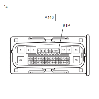
(c) Disconnect the A140 skid control ECU (brake actuator assembly) connector.
(d) Check both the connector case and the terminals for deformation and corrosion.
OK:
No deformation or corrosion.
(e) Measure the voltage according to the value(s) in the table below.
Standard Voltage:
|
Tester Connection |
Condition |
Specified Condition |
|---|---|---|
|
A140-11 (STP) - Body ground |
Stop light switch assembly on (Brake pedal depressed) |
8 to 14 V |
|
A140-11 (STP) - Body ground |
Stop light switch assembly off (Brake pedal released) |
Below 1.5 V |
| NG |
|
REPAIR OR REPLACE HARNESS OR CONNECTOR |
|
|
7. |
CLEAR DTC |
(a) Reconnect the A140 skid control ECU (brake actuator assembly) connector.
(b) Clear the DTCs.
Chassis > Brake/EPB > Clear DTCs
(c) Turn the ignition switch off.
|
|
8. |
RECONFIRM DTC |
(a) Based on the Freeze Frame Data and interview with the customer, attempt to reproduce the conditions when the malfunction occurred.
(b) Check if the same DTC is output.
Chassis > Brake/EPB > Trouble Codes
|
Result |
Proceed to |
|---|---|
|
DTC P057111 is not output. |
A |
|
DTC P057111 is output. |
B |
| A |
|
| B |
|
REPLACE BRAKE ACTUATOR ASSEMBLY
Click here
|
|
9. |
INSPECT STOP LIGHT SWITCH ASSEMBLY |
Click here
OK:
The stop light switch assembly is normal.
| NG |
|
|
|
10. |
CHECK HARNESS AND CONNECTOR (STP TERMINAL) |
|
(a) Turn the ignition switch off. |
|
(b) Make sure that there is no looseness at the locking part and the connecting part of the connectors.
OK:
The connector is securely connected.
(c) Disconnect the A140 skid control ECU (brake actuator assembly) connector.
(d) Check both the connector case and the terminals for deformation and corrosion.
OK:
No deformation or corrosion.
(e) Measure the voltage according to the value(s) in the table below.
Standard Voltage:
|
Tester Connection |
Condition |
Specified Condition |
|---|---|---|
|
A140-11 (STP) - Body ground |
Stop light switch assembly on (Brake pedal depressed) |
8 to 14 V |
|
A140-11 (STP) - Body ground |
Stop light switch assembly off (Brake pedal released) |
Below 1.5 V |
| NG |
|
REPAIR OR REPLACE HARNESS OR CONNECTOR |
|
|
11. |
CLEAR DTC |
(a) Reconnect the A140 skid control ECU (brake actuator assembly) connector.
(b) Clear the DTCs.
Chassis > Brake/EPB > Clear DTCs
(c) Turn the ignition switch off.
|
|
12. |
RECONFIRM DTC |
(a) Based on the Freeze Frame Data and interview with the customer, attempt to reproduce the conditions when the malfunction occurred.
(b) Check if the same DTC is output.
Chassis > Brake/EPB > Trouble Codes
|
Result |
Proceed to |
|---|---|
|
DTC P057111 is not output. |
A |
|
DTC P057111 is output. |
B |
| A |
|
| B |
|
REPLACE BRAKE ACTUATOR ASSEMBLY
Click here
|
|
|
|