| Last Modified: 05-13-2024 | 6.11:8.1.0 | Doc ID: RM1000000025UOC |
| Model Year Start: 2023 | Model: GR Corolla | Prod Date Range: [09/2022 - ] |
| Title: EA67F / EA68F (MANUAL TRANSMISSION / TRANSAXLE): MANUAL TRANSAXLE SYSTEM: Pattern Select Switch iMT Mode Circuit; 2023 - 2025 MY Corolla Corolla Hatchback GR Corolla [09/2022 - ] | ||
|
Pattern Select Switch iMT Mode Circuit |
DESCRIPTION
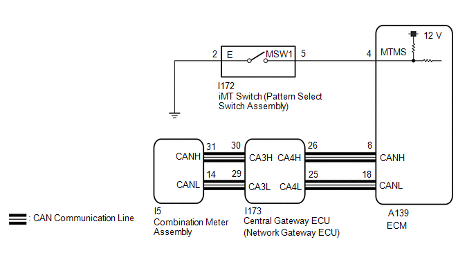
When the iMT switch (pattern select switch assembly) is operated to turn the iMT system on, the iMT indicator (green) in the combination meter assembly illuminates.
When the iMT indicator (green) is illuminated, the iMT system is in standby.
WIRING DIAGRAM

PROCEDURE
|
1. |
CHECK DTC OUTPUT (SFI SYSTEM) |
(a) Check for SFI system DTCs.
Powertrain > Engine > Trouble Codes
|
Result |
Proceed to |
|---|---|
|
DTCs are not output |
A |
|
DTCs are output |
B |
| B |

|
|
|
2. |
INSPECT iMT SWITCH (PATTERN SELECT SWITCH ASSEMBLY) |
|
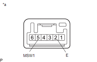
(a) Remove the iMT switch (pattern select switch assembly). |
|
(b) Measure the resistance according to the value(s) in the table below.
Standard Resistance:
|
Tester Connection |
Condition |
Specified Condition |
|---|---|---|
|
5 (MSW1) - 2 (E) |
Switch pushed |
Below 1 Ω |
|
5 (MSW1) - 2 (E) |
Switch not pushed |
10 kΩ or higher |
(c) Install the iMT switch (pattern select switch assembly).
| NG |

|
|
|
3. |
CHECK HARNESS AND CONNECTOR (iMT SWITCH (PATTERN SELECT SWITCH ASSEMBLY)) - BODY GROUND) |
(a) Disconnect the I172 iMT switch (pattern select switch assembly) connector.
(b) Measure the resistance according to the value(s) in the table below.
Standard Resistance:
|
Tester Connection |
Condition |
Specified Condition |
|---|---|---|
|
I172-2 (E) - Body ground |
Always |
Below 1 Ω |
(c) Connect the I172 iMT switch (pattern select switch assembly) connector.
| NG |

|
REPAIR OR REPLACE HARNESS OR CONNECTOR |
|
|
4. |
CHECK HARNESS AND CONNECTOR (PATTERN SELECT SWITCH ASSEMBLY (iMT SWITCH) - ECM) |
(a) Disconnect the I172 iMT switch (pattern select switch assembly) connector.
(b) Disconnect the A139 ECM connector.
(c) Measure the resistance according to the value(s) in the table below.
Standard Resistance:
|
Tester Connection |
Condition |
Specified Condition |
|---|---|---|
|
I172-5 (MSW1) -A139-4 (MTMS) |
Always |
Below 1 Ω |
|
I172-5 (MSW1) or A139-4 (MTMS) - Body ground |
Always |
10 kΩ or higher |
(d) Connect the A139 ECM connector.
(e) Connect the I172 iMT switch (pattern select switch assembly) connector.
| OK |

|
| NG |

|
REPAIR OR REPLACE HARNESS OR CONNECTOR |
|
|
|


![2023 MY GR Corolla [09/2022 - 11/2022]; G16E-GTS (ENGINE CONTROL): ECM: REMOVAL](/t3Portal/stylegraphics/info.gif)