| Last Modified: 05-13-2024 | 6.11:8.1.0 | Doc ID: RM1000000025TEA |
| Model Year Start: 2023 | Model: Corolla Hatchback | Prod Date Range: [09/2022 - ] |
| Title: PA10 (HYBRID TRANSMISSION / TRANSAXLE): SHIFT LEVER: INSPECTION; 2023 - 2025 MY Corolla Corolla Hatchback Corolla HV [09/2022 - ] | ||
INSPECTION
PROCEDURE
1. INSPECT SHIFT LOCK CONTROL ECU (w/ Smart Key System)
HINT:
If the results of the following inspections are as specified but a malfunction has occurred, replace the shift lock control unit assembly.
(a) Inspect wire harness:
|
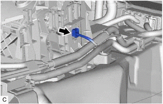
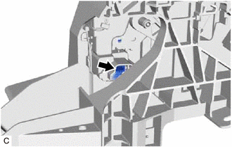
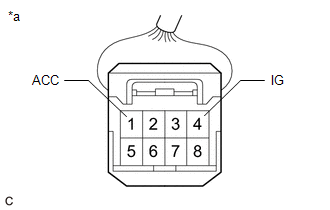
(1) Disconnect the shift lock control ECU connector. |
|
|
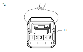
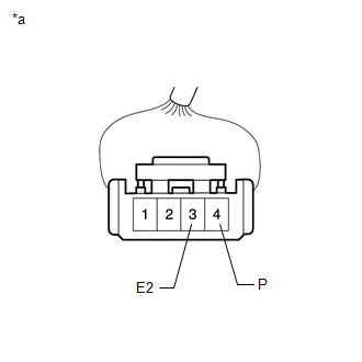
(2) Measure the voltage according to the value(s) in the table below. Standard Voltage:
If the result is not as specified, repair or replace the shift lock control ECU wire harness. |
|
|
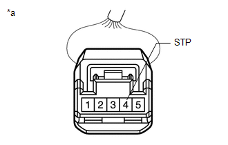
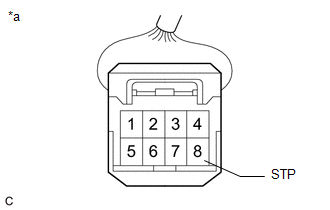
(3) Measure the voltage according to the value(s) in the table below. Standard Voltage:
If the result is not as specified, repair or replace the wire harness or connector or replace the hybrid vehicle control ECU assembly. |
|
|
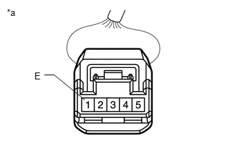
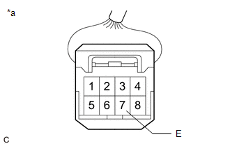
(4) Measure the resistance according to the value(s) in the table below. Standard Resistance:
If the result is not as specified, repair or replace the shift lock control ECU wire harness. |
|
(b) Inspect shift lock solenoid:
|
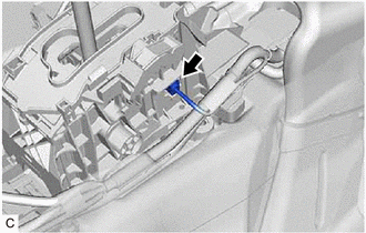
(1) Disconnect the shift lock solenoid connector. |
|
|
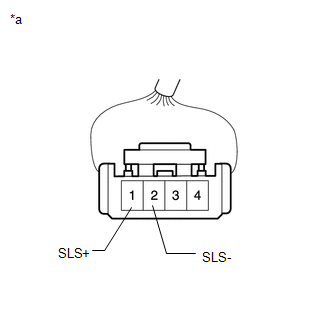
(2) Measure the resistance according to the value(s) in the table below. Standard Resistance:
If the result is not as specified, replace the shift lock control unit assembly. |
|
|
(3) Measure the resistance according to the value(s) in the table below. Standard Resistance:
If the result is not as specified, replace the shift lock control unit assembly. |
|
2. INSPECT SHIFT LOCK CONTROL ECU (w/o Smart Key System)
HINT:
If the results of the following inspections are as specified but a malfunction has occurred, replace the shift lock control unit assembly.
(a) Inspect wire harness:
|
(1) Disconnect the shift lock control ECU connector. |
|
|
(2) Measure the voltage according to the value(s) in the table below. Standard Voltage:
If the result is not as specified, repair or replace the shift lock control ECU wire harness. |
|
|
(3) Measure the voltage according to the value(s) in the table below. Standard Voltage:
If the result is not as specified, repair or replace the wire harness or connector or replace the hybrid vehicle control ECU assembly. |
|
|
(4) Measure the resistance according to the value(s) in the table below. Standard Resistance:
If the result is not as specified, repair or replace the shift lock control ECU wire harness. |
|
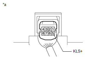
(b) Inspect key interlock solenoid operation signal:
|
(1) Connect the shift lock control ECU connector. |
|
|
(2) Measure the voltage according to the value(s) in the table below. Standard Voltage:
HINT: Do not disconnect the shift lock control ECU connector. If the result is not as specified, replace the shift lock control unit assembly. |
|
(c) Inspect shift lock solenoid:
|
(1) Disconnect the shift lock solenoid connector. |
|
|
(2) Measure the resistance according to the value(s) in the table below. Standard Resistance:
If the result is not as specified, replace the shift lock control unit assembly. |
|
|
(3) Measure the resistance according to the value(s) in the table below. Standard Resistance:
If the result is not as specified, replace the shift lock control unit assembly. |
|
|
|
|