- Resolver learning
- Initialize resolver
| Last Modified: 07-31-2024 | 6.11:8.1.0 | Doc ID: RM1000000025SQK |
| Model Year Start: 2023 | Model: Corolla | Prod Date Range: [09/2022 - 11/2022] |
| Title: Q810 (HYBRID TRANSMISSION / TRANSAXLE): REAR TRACTION MOTOR: REMOVAL; 2023 MY Corolla Corolla HV [09/2022 - 11/2022] | ||
REMOVAL
CAUTION / NOTICE / HINT
The necessary procedures (adjustment, calibration, initialization or registration) that must be performed after parts are removed and installed, or replaced during rear traction motor with transaxle assembly removal/installation are shown below.
Necessary Procedures after parts removed/installed/replaced
|
Replaced Part or Performed Procedure |
Necessary Procedure |
Effect/Inoperative Function when Necessary Procedure not Performed |
Link |
|---|---|---|---|
|
Replacement of rear traction motor with transaxle assembly |
|
|
|
|
Rear wheel alignment adjustment |
|
|
|
|
Gas leak from exhaust system is repaired |
Inspection after repair |
|
CAUTION:
-
Orange wire harnesses and connectors indicate high-voltage circuits. To prevent electric shock, always follow the procedure described in the repair manual.
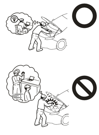
-
To prevent electric shock, wear insulated gloves when working on wire harnesses and components of the high voltage system.
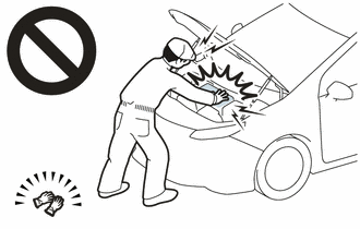
-
To prevent burns, do not touch the engine, exhaust pipe or other high temperature components while the engine is hot.
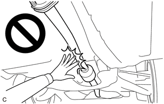
HINT:
When the cable is disconnected / reconnected to the auxiliary battery terminal, systems temporarily stop operating. However, each system has a function that completes learning the first time the system is used.
Learning completes when vehicle is driven
|
Effect/Inoperative Function when Necessary Procedure not Performed |
Necessary Procedure |
Link |
|---|---|---|
|
Front Camera System (for TMC Made) |
Drive the vehicle straight ahead at 15 km/h (9 mph) or more for 1 second or more. |
PROCEDURE
1. PERFORM RESOLVER INITIALIZATION
NOTICE:
If it is necessary to replace the rear traction motor with transaxle assembly, make sure to perform resolver initialization before starting work.
2. REMOVE SERVICE PLUG GRIP
3. REMOVE CONNECTOR COVER ASSEMBLY
4. CHECK TERMINAL VOLTAGE
5. INSTALL CONNECTOR COVER ASSEMBLY
6. REMOVE SPARE WHEEL COVER
7. REMOVE SPARE WHEEL CUSHION
(a) Remove the spare wheel cushion.
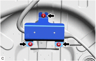
8. REMOVE MOTOR CONNECTOR PROTECTOR
|
(a) Remove the 3 nuts and motor connector protector from the vehicle body. |
|
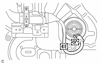
9. DISCONNECT REAR TRACTION MOTOR CABLE
|
(a) Disengage the 2 clamps to disconnect the rear traction motor cable from the vehicle body. |
|
|
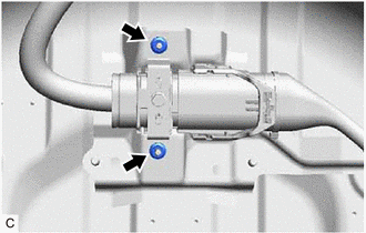
(b) Remove the 2 nuts to disconnect the radio earth bracket from the vehicle body. |
|
(c) Disconnect the rear traction motor cable connector.
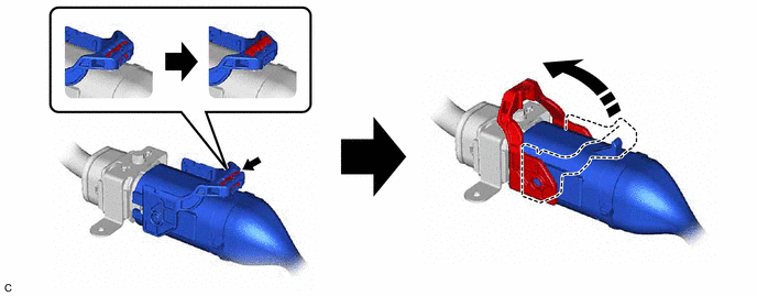
HINT:
Release the lock before rotating the lock lever.
|
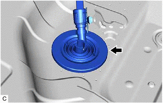
(d) Separate the grommet of the rear traction motor cable from the vehicle body and push out the rear traction motor cable from the cabin. |
|
10. REMOVE REAR SUSPENSION MEMBER SUB-ASSEMBLY
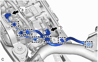
11. REMOVE NO. 6 FLOOR WIRE
|
(a) Disconnect the motor temperature sensor connector. |
|
(b) Disconnect the motor resolver sensor connector.
(c) Disengage the 7 clamps to remove the No. 6 floor wire.
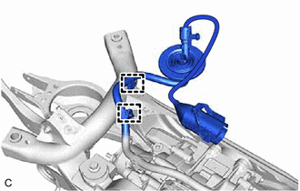
12. DISCONNECT REAR TRACTION MOTOR CABLE
|
(a) Disengage the 2 clamps to disconnect the rear traction motor cable. |
|
13. REMOVE REAR TRACTION MOTOR WITH TRANSAXLE ASSEMBLY
(a) Using a mini crane and 2 belt slings, hold the rear traction motor with transaxle assembly.
CAUTION:
- Do not lift the rear traction motor with transaxle assembly more than necessary.
- When lifting the rear traction motor with transaxle assembly, make sure it is well balanced.
NOTICE:
- Lightly shake the rear traction motor with transaxle assembly by hand to make sure it is securely held while performing work.
- Do not shake the rear traction motor with transaxle assembly excessively while holding it.
(b) Remove the 4 bolts, 2 upper differential mount stoppers, 2 lower differential mount stoppers, differential mass damper and rear traction motor with transaxle assembly from the rear suspension member sub-assembly.
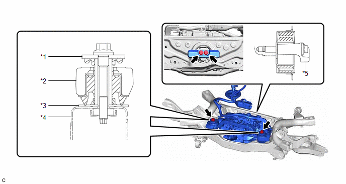
|
*1 |
Upper Differential Mount Stopper |
*2 |
Front Differential Support Assembly |
|
*3 |
Lower Differential Mount Stopper |
*4 |
Rear Suspension Member Sub-assembly |
|
*5 |
Differential Mass Damper |
- |
- |
NOTICE:
- Be careful not to drop the rear traction motor with transaxle assembly.
- Be careful not to damage the installation surfaces of the rear traction motor with transaxle assembly when removing it.
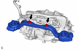
14. REMOVE FRONT DIFFERENTIAL SUPPORT ASSEMBLY
|
(a) Remove the 2 bolts and front differential support assembly from the rear traction motor with transaxle assembly. |
|
15. REMOVE REAR TRACTION MOTOR CABLE
16. REMOVE MOTOR CABLE BRACKET
(a) Remove the 3 bolts and 3 motor cable brackets from the rear traction motor with transaxle assembly.

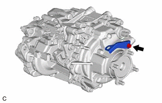
17. REMOVE WIRE HARNESS CLAMP BRACKET
|
(a) Remove the bolt and wire harness clamp bracket from the rear traction motor with transaxle assembly. |
|
18. REMOVE DIFFERENTIAL DYNAMIC DAMPER
HINT:
- Perform this procedure only when replacement of the differential dynamic damper is necessary.
-
The illustration shown is an example only. The illustration may differ from the actual parts according to the model.
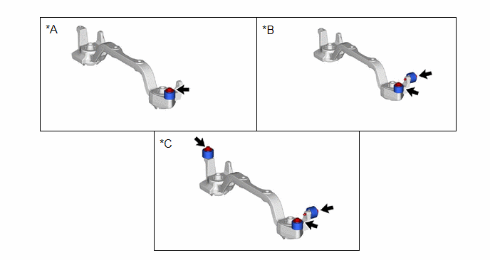
*A
for Type A
*B
for Type B
*C
for Type C
-
-
(a) Remove the bolts and differential dynamic dampers from the front differential support assembly.
for Type A:

for Type B:

for Type C:

|
|
|
![2023 - 2025 MY Corolla HV [09/2022 - ]; HYBRID / BATTERY CONTROL: MOTOR GENERATOR CONTROL SYSTEM (for LITHIUM-ION BATTERY with PA10): UTILITY](/t3Portal/stylegraphics/info.gif)
