| Last Modified: 07-31-2024 | 6.11:8.1.0 | Doc ID: RM1000000025P1F |
| Model Year Start: 2023 | Model: Corolla | Prod Date Range: [09/2022 - ] |
| Title: 2ZR-FXE (EMISSION CONTROL): EGR COOLER: INSTALLATION; 2023 - 2025 MY Corolla Corolla HV [09/2022 - ] | ||
INSTALLATION
PROCEDURE
1. INSTALL EGR PIPE WITH COOLER SUB-ASSEMBLY
|
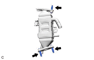
(a) Using an E8 "TORX" socket wrench, install the 3 stud bolts to the EGR pipe with cooler sub-assembly. HINT: If a stud bolt is deformed or the threads are damaged, replace it. Torque: 5.0 N·m {51 kgf·cm, 44 in·lbf} |
|
(b) Install a new EGR valve gasket to the EGR valve assembly.
(c) Install the EGR pipe with cooler sub-assembly to the EGR valve assembly with the 2 nuts.
Torque:
21 N·m {214 kgf·cm, 15 ft·lbf}
|
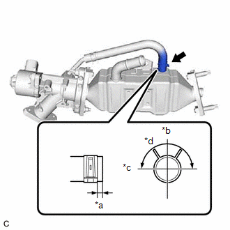
(d) Connect the No. 6 water by-pass hose to the EGR pipe with cooler sub-assembly and slide the clip to secure it. HINT: Engage the clip within the area shown in the illustration. |
|
(e) Install a new EGR cooler gasket to the EGR pipe with cooler sub-assembly.
(f) Set the EGR pipe with cooler sub-assembly with the EGR valve assembly to the engine assembly.
|
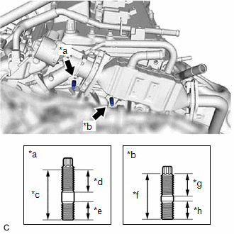
(g) Using an E8 "TORX" socket wrench, install the stud bolt (A) and stud bolt (B) to the cylinder head sub-assembly and camshaft housing sub-assembly. HINT: If a stud bolt is deformed or the threads are damaged, replace it. Torque: 9.5 N·m {97 kgf·cm, 84 in·lbf} |
|
(h) Temporarily install the EGR pipe with cooler sub-assembly with the EGR valve assembly to the cylinder head sub-assembly and camshaft housing sub-assembly with the bolt and 2 nuts.
(i) Temporarily install the EGR pipe with cooler sub-assembly to the exhaust manifold (TWC: Front Catalyst) with 2 new nuts.
(j) Tighten the bolt and 2 nuts.
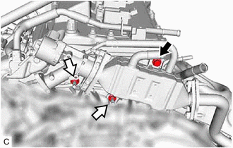

|
Bolt |

|
Nut |
Torque:
21 N·m {214 kgf·cm, 15 ft·lbf}
|
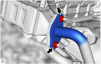
(k) Tighten the 2 nuts. Torque: 26 N·m {265 kgf·cm, 19 ft·lbf} |
|
(l) Connect the EGR valve assembly connector.
2. CONNECT NO. 4 WATER BY-PASS HOSE
|
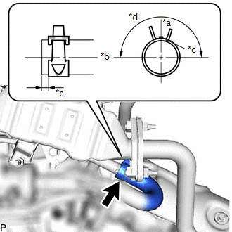
(a) Connect the No. 4 water by-pass hose to the EGR pipe with cooler sub-assembly and slide the clip to secure it. HINT: Engage the clip within the area shown in the illustration. |
|
3. CONNECT INLET HEATER WATER HOSE
|
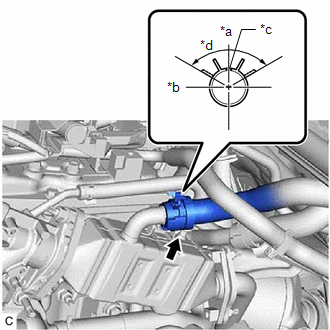
(a) Connect the inlet heater water hose to the EGR pipe with cooler sub-assembly and slide the clip to secure it. HINT: Engage the clip within the area shown in the illustration. |
|
4. CONNECT WATER BY-PASS HOSE
|
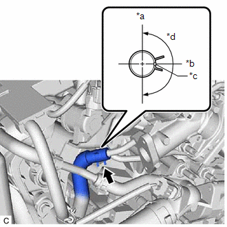
(a) Connect the water by-pass hose to the EGR valve assembly and slide the clip to secure it. HINT: Engage the clip within the area shown in the illustration. |
|
5. INSTALL EGR PIPE ASSEMBLY
6. INSTALL INVERTER WITH CONVERTER ASSEMBLY
7. ADD ENGINE COOLANT (for Engine)
8. INSPECT FOR COOLANT LEAK (for Engine)
9. INSPECT FOR EXHAUST GAS LEAK
|
|
|
![2023 - 2025 MY Corolla Corolla HV [09/2022 - ]; 2ZR-FXE (INTAKE / EXHAUST): INTAKE MANIFOLD: INSTALLATION+](/t3Portal/stylegraphics/info.gif)