| Last Modified: 05-13-2024 | 6.11:8.1.0 | Doc ID: RM1000000025IF3 |
| Model Year Start: 2023 | Model: GR Corolla | Prod Date Range: [09/2022 - ] |
| Title: EXTERIOR PANELS / TRIM: GRILLE SHUTTER SYSTEM: Grille Shutter does not Operate; 2023 - 2025 MY Corolla Corolla Hatchback Corolla HV GR Corolla [09/2022 - ] | ||
|
Grille Shutter does not Operate |
DESCRIPTION
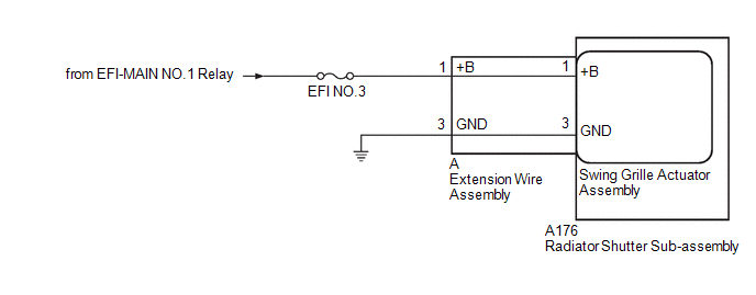
The radiator shutter sub-assembly may not operate due to foreign matter, such as snow or dirt, or a drop in voltage.
WIRING DIAGRAM

CAUTION / NOTICE / HINT
NOTICE:
- Before performing troubleshooting, change the grille shutter control mode to maintenance mode.
- If the radiator shutter sub-assembly has been replaced with a new one, perform initialization and change the grille shutter control mode.
- Inspect the fuses for circuits related to this system before performing the following procedure.
PROCEDURE
|
1. |
PERFORM UTILITY USING GTS (SWITCH GRILLE SHUTTER CONTROL MODE) |
(a) According to the display on the GTS, change the grille shutter control mode from normal mode to maintenance mode.
Powertrain > Engine > Utility
|
Tester Display |
|---|
|
Switch Grille Shutter Control Mode |
|
|
2. |
CHECK FOR GRILLE SHUTTER (FOREIGN MATTER AND ICE) |
(a) Check the area around the shutters and the links of the grille shutter for foreign matter and ice.
OK:
The radiator shutter sub-assembly is free of foreign matter and ice.
| NG |

|
FOREIGN OBJECT (REMOVE FOREIGN MATTER AND/OR ICE) |
|
|
3. |
CHECK RADIATOR SHUTTER SUB-ASSEMBLY |
(a) Remove the radiator shutter sub-assembly.
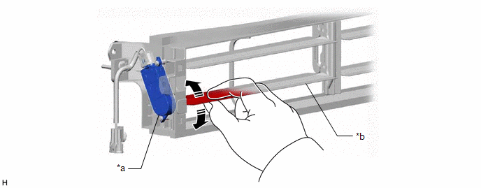
(b) While using fingers to pinch the fin at the location shown in the illustration, fully open and close the radiator shutter assembly manually and check that it moves smoothly.
HINT:
If the fin is pinched with fingers far from the swing grille actuator assembly, the function may not be able to be inspected correctly.

|
*a |
Swing Grille Actuator Assembly |
*b |
Fin |
OK:
The radiator shutter sub-assembly moves smoothly.
| NG |

|
|
|
4. |
CLEAR DTC |
(a) Clear the DTCs.
Powertrain > Engine > Clear DTCs
(b) Turn the power switch off and wait for at least 30 seconds.
|
|
5. |
CHECK FOR DTC |
(a) Check for DTCs.
Powertrain > Engine > Trouble Codes
OK:
DTCs are not output.
| NG |

|
|
|
6. |
CHECK HARNESS AND CONNECTOR (EXTENSION WIRE ASSEMBLY - POWER SUPPLY AND BODY GROUND) |
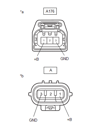
(a) Disconnect the A extension wire assembly connector.
(b) Measure the voltage according to the value(s) in the table below.
Standard Voltage:
|
Tester Connection |
Switch Condition |
Specified Condition |
|---|---|---|
|
A-1 (+B) - A-3 (GND) |
Power switch ON |
11 to 14 V |
| NG |

|
REPAIR OR REPLACE HARNESS OR CONNECTOR |
|
|
7. |
INSPECT EXTENSION WIRE ASSEMBLY |
(a) Remove the extension wire assembly.
|
(b) Measure the resistance according to the value(s) in the table below. Standard Resistance:
|
|
| OK |

|
| NG |

|
|
|
|
![2023 - 2025 MY Corolla Corolla HV [09/2022 - ]; 2ZR-FXE (ENGINE CONTROL): SFI SYSTEM: INITIALIZATION](/t3Portal/stylegraphics/info.gif)

