| Last Modified: 05-13-2024 | 6.11:8.1.0 | Doc ID: RM1000000025DUI |
| Model Year Start: 2023 | Model: Corolla | Prod Date Range: [09/2022 - ] |
| Title: BRAKE CONTROL / DYNAMIC CONTROL SYSTEMS: ELECTRONICALLY CONTROLLED BRAKE SYSTEM (for HV Model): C137BA3; Brake System Control Module "A" System Voltage System Voltage High; 2023 - 2025 MY Corolla Corolla HV [09/2022 - ] | ||
|
DTC |
C137BA3 |
Brake System Control Module "A" System Voltage System Voltage High |
DESCRIPTION
If a malfunction is detected in the power supply circuit, the skid control ECU (brake actuator assembly) stores this DTC and the fail-safe function prohibits ABS, brake assist, regenerative braking, etc. operation.
This DTC is stored when the +BS terminal voltage deviates due to a malfunction in a power supply or charging system circuit such as the auxiliary battery or DC/DC converter circuit, etc.
|
DTC No. |
Detection Item |
DTC Detection Condition |
Trouble Area |
MIL |
DTC Output from |
Note |
|---|---|---|---|---|---|---|
|
C137BA3 |
Brake System Control Module "A" System Voltage System Voltage High |
+BS terminal voltage is more than 16.5 V for 1 second or more. |
|
Comes on |
Brake/EPB |
|
MONITOR DESCRIPTION
When the supply voltage of the skid control ECU (brake actuator assembly) exceeds a certain value for a certain amount of time, the skid control ECU (brake actuator assembly) illuminates the MIL and stores this DTC.
MONITOR STRATEGY
|
Related DTCs |
C137D: Supply voltage monitoring (over voltage) |
|
Required Sensors/Components(Main) |
Skid control ECU (brake actuator assembly) |
|
Required Sensors/Components(Related) |
Skid control ECU (brake actuator assembly) |
|
Frequency of Operation |
Continuous |
|
Duration |
1 second |
|
MIL Operation |
2 driving cycles |
|
Sequence of Operation |
None |
TYPICAL ENABLING CONDITIONS
|
Monitor runs whenever the following DTCs are not stored |
TMC's intellectual property |
|
Other conditions belong to TMC's intellectual property |
- |
TYPICAL MALFUNCTION THRESHOLDS
|
TMC's intellectual property |
- |
COMPONENT OPERATING RANGE
|
TMC's intellectual property |
- |
CONFIRMATION DRIVING PATTERN
NOTICE:
When performing the normal judgment procedure, make sure that the driver door is closed and is not opened at any time during the procedure.
HINT:
- After repair has been completed, clear the DTC and then check that the vehicle has returned to normal by performing the following All Readiness check procedure.
- When clearing the permanent DTCs, refer to the "CLEAR PERMANENT DTC" procedure.
- Connect the GTS to the DLC3.
- Turn the ignition switch to ON and turn the GTS on.
- Clear the DTCs (even if no DTCs are stored, perform the clear DTC procedure).
- Turn the ignition switch off.
- Turn the ignition switch to ON (READY) and turn the GTS on.
-
Wait for 1 second or more. [*]
HINT:
[*]: Normal judgment procedure.
The normal judgment procedure is used to complete DTC judgment and also used when clearing permanent DTCs.
-
Enter the following menus: Chassis / Brake/EPB* / Utility / All Readiness.
*: Electric Parking Brake System
-
Check the DTC judgment result.
HINT:
- If the judgment result shows NORMAL, the system is normal.
- If the judgment result shows ABNORMAL, the system has a malfunction.
- If the judgment result shows INCOMPLETE, perform driving pattern again.
WIRING DIAGRAM
Refer to DTC C117A49
Click here
![2023 - 2025 MY Corolla Corolla HV [09/2022 - ]; BRAKE CONTROL / DYNAMIC CONTROL SYSTEMS: ELECTRONICALLY CONTROLLED BRAKE SYSTEM (for HV Model): C117A49,C137BA2; Brake System Control Module "A" System Voltage Line Internal Electronic Failure](/t3Portal/stylegraphics/info.gif)
CAUTION / NOTICE / HINT
NOTICE:
- Inspect the fuses for circuits related to this system before performing the following procedure.
-
Before performing troubleshooting, make sure to confirm that the auxiliary battery voltage is normal.
Click here
PROCEDURE
|
1. |
CHECK HARNESS AND CONNECTOR (+BS TERMINAL) |
|
(a) Make sure that there is no looseness at the locking part and the connecting part of the connector. OK: The connector is securely connected. |
|
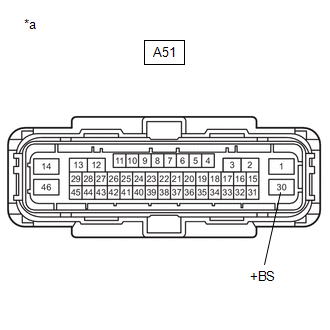
(b) Disconnect the A51 skid control ECU (brake actuator assembly) connector.
(c) Check both the connector case and the terminals for deformation and corrosion.
OK:
No deformation or corrosion.
(d) Measure the voltage according to the value(s) in the table below.
Standard Voltage:
|
Tester Connection |
Condition |
Specified Condition |
|---|---|---|
|
A51-30 (+BS) - Body ground |
Always |
11 to 14 V |
| OK |

|
| NG |
|
REPAIR OR REPLACE HARNESS OR CONNECTOR |
|
|
|