| Last Modified: 06-05-2026 | 6.11:8.1.0 | Doc ID: RM1000000025DI0 |
| Model Year Start: 2023 | Model: GR Corolla | Prod Date Range: [09/2022 - 11/2022] |
| Title: LIGHTING (EXT): LIGHTING SYSTEM (for TMMMS Made): High Beam Headlight Circuit; 2023 MY GR Corolla Corolla Corolla Hatchback Corolla HV [09/2022 - 11/2022] | ||
|
High Beam Headlight Circuit |
DESCRIPTION
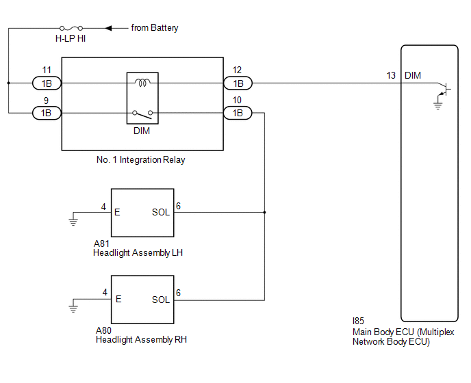
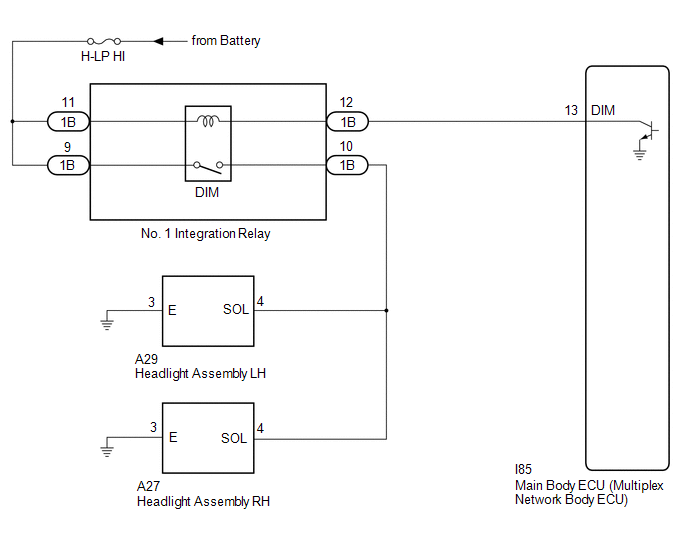
The main body ECU (multiplex network body ECU) controls the high beam headlights.
WIRING DIAGRAM
1. for LED Type Turn Signal Light
2. for Bulb Type Turn Signal Light
CAUTION / NOTICE / HINT
NOTICE:
- Inspect the fuses for circuits related to this system before performing the following procedure.
-
Before replacing the main body ECU (multiplex network body ECU), refer to Registration.*
Click here
![2023 MY GR Corolla Corolla Corolla Hatchback [09/2022 - 11/2022]; THEFT DETERRENT / KEYLESS ENTRY: SMART KEY SYSTEM (for Start Function (Gasoline Model, TMMMS Made)): REGISTRATION](/t3Portal/stylegraphics/info.gif)
-
Check the operation of the low beam headlights. If the low beam headlights do not operate normally, refer to Problem Symptoms Table.
Click here
- *: w/ Smart Key System
PROCEDURE
|
1. |
PERFORM ACTIVE TEST USING TECHSTREAM |
(a) Connect the Techstream to the DLC3.
(b) Turn the ignition switch to ON.
(c) Turn the Techstream on.
(d) Enter the following menus: Body Electrical / Main Body / Active Test.
(e) Perform the Active Test according to the display on the Techstream.
Body Electrical > Main Body > Active Test
|
Tester Display |
Measurement Item |
Control Range |
Diagnostic Note |
|---|---|---|---|
|
Head Light Hi |
High beam headlights |
OFF or ON |
- |
Body Electrical > Main Body > Active Test
OK:
High beam headlights illuminate.
| OK |

|
PROCEED TO NEXT SUSPECTED AREA SHOWN IN PROBLEM SYMPTOMS TABLE |
|

|
2. |
INSPECT NO. 1 INTEGRATION RELAY |
(a) Remove the No. 1 integration relay.
Click here
(b) Inspect the No. 1 integration relay.
Click here
| NG |
|
|
|
3. |
CHECK HARNESS AND CONNECTOR (POWER SOURCE - NO. 1 INTEGRATION RELAY) |
(a) Measure the voltage according to the value(s) in the table below.
Standard Voltage
|
Tester Connection |
Condition |
Specified Condition |
|---|---|---|
|
1B-9 - Body ground |
Always |
11 to 14 V |
|
1B-11 - Body ground |
Always |
11 to 14 V |
| NG |
|
REPAIR OR REPLACE HARNESS OR CONNECTOR |
|
|
4. |
CHECK HARNESS AND CONNECTOR (NO. 1 INTEGRATION RELAY - MAIN BODY ECU (MULTIPLEX NETWORK BODY ECU)) |
(a) Disconnect the I85 main body ECU (multiplex network body ECU) connector.
(b) Measure the resistance according to the value(s) in the table below.
Standard Resistance
|
Tester Connection |
Condition |
Specified Condition |
|---|---|---|
|
1B-12 - I85-13 (DIM) |
Always |
Below 1 Ω |
|
1B-12 or I85-13 (DIM) - Body ground |
Always |
10 kΩ or higher |
|
|

|

|