| Last Modified: 05-13-2024 | 6.11:8.1.0 | Doc ID: RM10000000259VR |
| Model Year Start: 2023 | Model: GR Corolla | Prod Date Range: [09/2022 - 11/2022] |
| Title: SUPPLEMENTAL RESTRAINT SYSTEMS: AIRBAG SYSTEM (for TMC Made): B009287; Left Side Restraints Sensor 2 Missing Message; 2023 MY Corolla Corolla Hatchback Corolla HV GR Corolla [09/2022 - 11/2022] | ||
|
DTC |
B009287 |
Left Side Restraints Sensor 2 Missing Message |
DESCRIPTION
|
DTC No. |
Detection Item |
DTC Detection Condition |
Trouble Area |
Warning Indicate |
DTC Output from |
Priority |
Test Mode / Check Mode |
|---|---|---|---|---|---|---|---|
|
B009287 |
Left Side Restraints Sensor 2 Missing Message |
|
|
Comes on |
SRS Airbag |
A |
Does not apply to test/check mode |
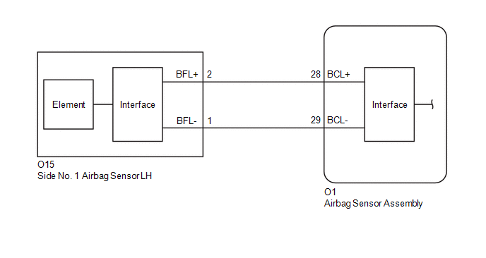
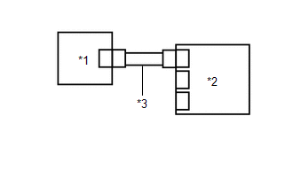
WIRING DIAGRAM
CAUTION / NOTICE / HINT
NOTICE:
-
After the ignition switch is turned off, there may be a waiting time before disconnecting the negative (-) auxiliary battery terminal.
Click here
![2023 - 2025 MY Corolla Corolla Hatchback Corolla HV GR Corolla [09/2022 - ]; SETUP: WHEN DISCONNECTING OR RECONNECTING BATTERY TERMINAL: BEFORE DISCONNECTING BATTERY](/t3Portal/stylegraphics/info.gif)
HINT:
When disconnecting and reconnecting the auxiliary battery, there is an automatic learning function that completes learning when the respective system is used.
Click here
-
After replacing the airbag sensor assembly, refer to work procedure.
Click here
PROCEDURE
|
1. |
CHECK CONNECTION OF CONNECTORS |
Pre-procedure1
(a) Turn the ignition switch off.
(b) Disconnect the cable from the negative (-) auxiliary battery terminal, and wait for at least 60 seconds.
Procedure1
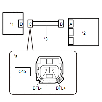
(c) Check that the connectors are properly connected to the airbag sensor assembly and side No. 1 airbag sensor LH.
OK:
The connectors are properly connected.
Post-procedure1
(d) None
| NG |

|
CONNECT CONNECTORS PROPERLY |
|

|
2. |
CHECK CONNECTORS |
Pre-procedure1
|
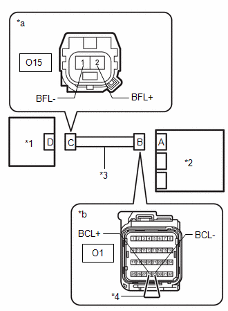
(a) Disconnect the airbag sensor assembly connector. |
|
(b) Disconnect the side No. 1 airbag sensor LH connector.
Procedure1
(c) Check that the terminals of the connectors are not deformed or damaged.
OK:
The terminals are not deformed or damaged.
Post-procedure1
(d) None
| NG |
|
REPAIR OR REPLACE HARNESS OR CONNECTOR |
|
|
3. |
CHECK HARNESS AND CONNECTOR (CHECK FOR SHORT IN THE CIRCUIT) |
|
(a) Measure the resistance according to the value(s) in the table below. Standard Resistance:
|
|
| NG |
|
REPAIR OR REPLACE HARNESS OR CONNECTOR |
|
|
4. |
CHECK HARNESS AND CONNECTOR (CHECK FOR OPEN IN THE CIRCUIT) |
Pre-procedure1
|
(a) Using a service wire, connect terminals 28 (BCL+) and 29 (BCL-) of connector B. NOTICE: Do not forcibly insert the service wire into the terminals of the connector when connecting a service wire. |
|
Procedure1
(b) Measure the resistance according to the value(s) in the table below.
Standard Resistance:
|
Tester Connection |
Condition |
Specified Condition |
|---|---|---|
|
O15-2 (BFL+) - O15-1 (BFL-) |
Always |
Below 1 Ω |
Post-procedure1
(c) Disconnect the service wire from connector B.
| NG |
|
REPAIR OR REPLACE HARNESS OR CONNECTOR |
|
|
5. |
CHECK HARNESS AND CONNECTOR (CHECK FOR SHORT TO GROUND IN THE CIRCUIT) |
|
(a) Measure the resistance according to the value(s) in the table below. Standard Resistance:
|
|
| NG |
|
REPAIR OR REPLACE HARNESS OR CONNECTOR |
|
|
6. |
CHECK HARNESS AND CONNECTOR (CHECK FOR SHORT TO +B IN THE CIRCUIT) |
Pre-procedure1
(a) Connect the cable to the negative (-) auxiliary battery terminal, and wait for at least 2 seconds.
(b) Turn the ignition switch to ON.
Procedure1
|
(c) Measure the voltage according to the value(s) in the table below. Standard Voltage:
Result:
|
|
Post-procedure1
(d) Turn the ignition switch off.
(e) Disconnect the cable from the negative (-) auxiliary battery terminal, and wait for at least 60 seconds.
| NG |
|
REPAIR OR REPLACE HARNESS OR CONNECTOR |
|
|
7. |
CLEAR DTC |
Pre-procedure1
|
(a) Connect the airbag sensor assembly connector. |
|
(b) Interchange the side No. 1 airbag sensor LH with RH and connect the connectors to them.
(c) Connect the cable to the negative (-) auxiliary battery terminal, and wait for at least 2 seconds.
(d) Turn the ignition switch to ON, and wait for at least 60 seconds.
Procedure1
(e) Clear the DTCs stored in memory.
Body Electrical > SRS Airbag > Clear DTCs
Post-procedure1
(f) Turn the ignition switch off.
|
|
8. |
CHECK SIDE NO. 1 AIRBAG SENSOR LH |
Pre-procedure1
(a) Turn the ignition switch to ON, and wait for at least 60 seconds.
Procedure1
(b) Check for DTCs.
Body Electrical > SRS Airbag > Trouble Codes
|
Result |
Proceed to |
|---|---|
|
B009287 is output |
A |
|
B009787 is output |
B |
|
B009287 and B009787 are not output |
C |
HINT:
Codes other than DTCs B009287 and B009787 may be output at this time, but they are not related to this check.
Post-procedure1
(c) Turn the ignition switch off.
(d) Disconnect the cable from the negative (-) auxiliary battery terminal, and wait for at least 60 seconds.
(e) Return the side No. 1 airbag sensor RH and LH to their original positions and connect the connectors to them.
| A |
|
| B |
|
| C |
|
|
|
|