
- Positive (+) tester probe → I4-6 (IG+)
- Negative (-) tester probe → I4-25 (SI)
| Last Modified: 05-13-2024 | 6.11:8.1.0 | Doc ID: RM10000000257AZ |
| Model Year Start: 2023 | Model: GR Corolla | Prod Date Range: [09/2022 - 11/2022] |
| Title: METER / GAUGE / DISPLAY: METER / GAUGE SYSTEM (except 12.3 Inch Display): Speed Signal Circuit; 2023 MY Corolla Corolla Hatchback Corolla HV GR Corolla [09/2022 - 11/2022] | ||
|
Speed Signal Circuit |
DESCRIPTION
SPEED SIGNAL CIRCUIT CONTROL
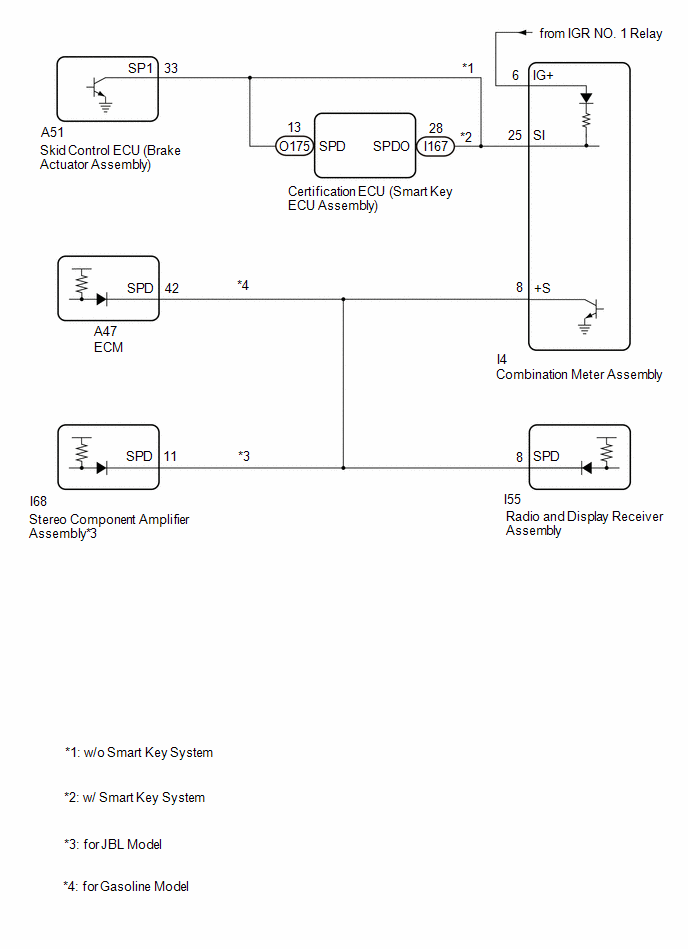
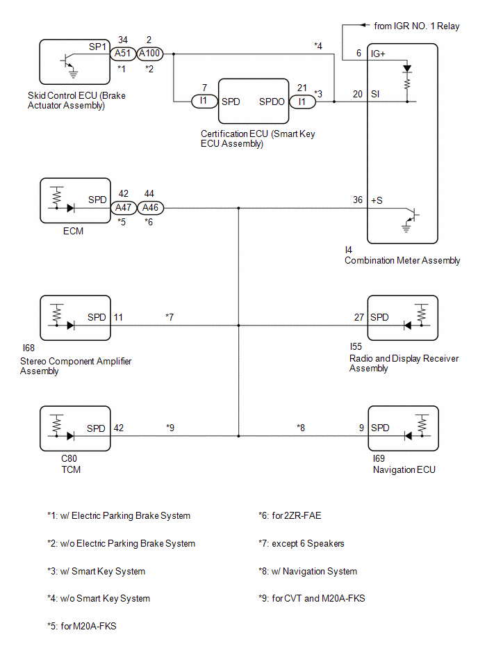
(a) The wheel speed sensors produce an output that varies according to the vehicle speed.
(b) The wheel speed sensor output is received by the skid control ECU (brake actuator assembly) which uses this information to create the vehicle speed signal.
(c) The vehicle speed signal is output from the skid control ECU (brake actuator assembly) to the certification ECU (smart key ECU assembly) and then to the combination meter assembly.
(d) To create this signal, 12 V is output from terminal SI of the combination meter assembly to the certification ECU (smart key ECU assembly).
(e) The pulse signal is created by switching the transistor in the certification ECU (smart key ECU assembly) on and off, making the voltage on the wire drop to 0 V.
(f) A similar system is used for the output of this signal from the combination meter assembly via terminal +S.
(g) A voltage of 12 V or 5 V is applied to terminal +S from each ECU or relay that is connected to this terminal.
(h) The transistor in the combination meter assembly is controlled by the signal from the certification ECU (smart key ECU assembly). When this transistor is turned on, this transistor makes the voltage supplied by the various ECUs (via their respective internal resistors) drop to 0 V.
(i) Each ECU connected to terminal +S of the combination meter assembly controls its respective system based on this pulse signal.
WIRING DIAGRAM
for TMC Made
for TMMMS Made
CAUTION / NOTICE / HINT
NOTICE:
- When replacing the combination meter assembly, always replace it with a new one. If a combination meter assembly which was installed to another vehicle is used, the information stored in it will not match the information from the vehicle and a DTC may be stored.
-
for TMC Made
When replacing the combination meter assembly, update the ECU security key.
Click here
![2023 - 2025 MY Corolla Corolla Hatchback Corolla HV GR Corolla [09/2022 - ]; SETUP: WHEN REPLACING OR REMOVING/INSTALLING PARTS: UPDATE ECU SECURITY KEY](/t3Portal/stylegraphics/info.gif)
- Combination meter assembly
- ECM*
-
Certification ECU (smart key ECU assembly)
- *: for Gasoline Model
-
When the electronically controlled brake system is malfunctioning, a correct vehicle speed signal may not be received. Before preforming this procedure, confirm that the electronically controlled brake system is not malfunctioning.
for HV Model: Click here
for Gasoline Model with Electric Parking Brake System TMMMS Made: Click here
for Gasoline Model without Electric Parking Brake System TMC Made: Click here
for Gasoline Model without Electric Parking Brake System TMMMS Made: Click here
-
Before replacing any of the following ECUs, refer to Registration.
- ECM*
-
Certification ECU (smart key ECU assembly)
HV Model Made: Click here
Gasoline Model, TMMMS Made: Click here
Gasoline Model, except TMMMS Made: Click here
- *: for Gasoline Model
PROCEDURE
|
1. |
CONFIRM MODEL |
(a) Choose the model to be inspected.
|
Result |
Proceed to |
|---|---|
|
for TMC Made |
A |
|
for TMMMS Made |
B |
| B |

|
|
|
2. |
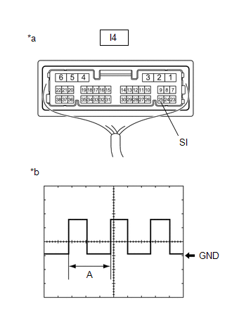
INSPECT COMBINATION METER ASSEMBLY (INPUT WAVEFORM) |
|
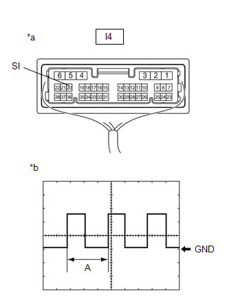
*a |
Component with harness connected (Combination Meter Assembly) |
|
*b |
Input Waveform |
(a) Check the signal waveform according to the condition(s) in the table below.
|
Item |
Condition |
|---|---|
|
Tester connection |
I4-25 (SI) - Body ground |
|
Tool setting |
5 V/DIV., 20 ms./DIV. |
|
Condition |
Ignition switch ON, wheel being rotated |
NOTICE:
Perform the inspection from the back of the connector with the connector connected.
HINT:
When the system is functioning normally, one wheel revolution generates 4 pulses. As the vehicle speed increases, the width indicated by (A) in the illustration narrows.
Result |
Proceed to |
|---|---|
|
The measured waveform is similar to that in the illustration |
A |
|
The measured waveform is not similar to that in the illustration (Stuck low) |
B |
|
The measured waveform is not similar to that in the illustration (Stuck high) |
C |
| B |
|
| C |
|
|
|
3. |
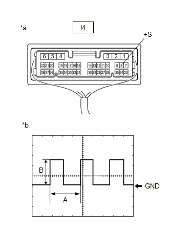
INSPECT COMBINATION METER ASSEMBLY (OUTPUT WAVEFORM) |
|
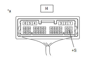
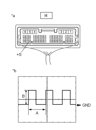
*a |
Component with harness connected (Combination Meter Assembly) |
|
*b |
Output Waveform |
(a) Check the signal waveform according to the condition(s) in the table below.
|
Item |
Condition |
|---|---|
|
Tester connection |
I4-8 (+S) - Body ground |
|
Tool setting |
5 V/DIV., 20 ms./DIV. |
|
Condition |
Ignition switch ON, wheel being rotated |
NOTICE:
Perform the inspection from the back of the connector with the connector connected.
HINT:
- When the system is functioning normally, one wheel revolution generates 4 pulses. As the vehicle speed increases, the width indicated by (A) in the illustration narrows.
- The waveform (B) changes depending on the connected ECUs.
Result |
Proceed to |
|---|---|
|
The measured waveform is similar to that in the illustration |
A |
|
The measured waveform is not similar to that in the illustration (Stuck low) |
B |
|
The measured waveform is not similar to that in the illustration (Stuck high) |
C |
| B |
|
| C |
|
|
|
4. |
CHECK HARNESS AND CONNECTOR (EACH ECU - COMBINATION METER ASSEMBLY) |
(a) Disconnect the A47 ECM*1 connector.
(b) Disconnect the I68 stereo component amplifier assembly*2 connector.
(c) Disconnect the I55 radio and display receiver assembly connector.
(d) Disconnect the I4 combination meter assembly connector.
(e) Measure the resistance according to the value(s) in the table below.
Standard Resistance:
|
Tester Connection |
Condition |
Specified Condition |
|---|---|---|
|
A47-42 (SPD) - I4-8 (+S)*1 |
Always |
Below 1 Ω |
|
I68-11 (SPD) - I4-8 (+S)*2 |
Always |
Below 1 Ω |
|
I55-27 (SPD) - I4-8 (+S) |
Always |
Below 1 Ω |
- *1: for M20A-FKS
- *2: for JBL Model
| OK |
|
CHECK THE VOLTAGE AT TERMINAL SPD OF EACH ECU |
| NG |
|
REPAIR OR REPLACE HARNESS OR CONNECTOR |
|
5. |
INSPECT EACH ECU (INTERNAL SHORT) |
|
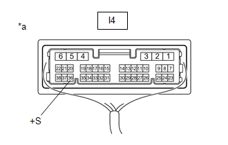
*a |
Component with harness connected (Combination Meter Assembly) |
(a) Disconnect one of the connectors below.
NOTICE:
After disconnecting a connector, perform all steps with all other ECUs connected.
|
Terminal No. (Symbol) |
ECU |
|---|---|
|
A47*1 |
ECM |
|
I68*2 |
Stereo component amplifier assembly |
|
I55 |
Radio and display receiver assembly |
- *1: for M20A-FKS
- *2: for JBL Model
(b) Measure the voltage according to the value(s) in the table below.
NOTICE:
- Make sure to perform this inspection with the wheels stopped.
- Perform the inspection from the back of the connector with the connector connected.
Standard Voltage:
|
Tester Connection |
Condition |
Specified Condition |
|---|---|---|
|
I4-8 (+S) - Body ground |
Ignition switch ON |
4.5 to 14 V |
(c) Repeat steps (a) and (b) for each connected ECU.
HINT:
If the waveform changes to the waveform shown in the illustration after disconnecting a connector, an internal short in the disconnected ECU is suspected.
Result |
Proceed to |
|---|---|
|
After performing the inspection procedure for all connectors, the voltage did not change to the specified voltage |
A |
|
When disconnecting the connector of the ECM, the voltage changed to the specified voltage |
B |
|
When disconnecting the connector of the stereo component amplifier assembly, the voltage changed to the specified voltage (for JBL Model) |
C |
|
When disconnecting the connector of the radio and display receiver assembly, the voltage changed to the specified voltage |
D |
| B |
|
| C |
|
| D |
|
|
|
6. |
CHECK HARNESS AND CONNECTOR (EACH ECU - COMBINATION METER ASSEMBLY) |
(a) Disconnect the A47 ECM*1 connector.
(b) Disconnect the I68 stereo component amplifier assembly*2 connector.
(c) Disconnect the I55 radio and display receiver assembly connector.
(d) Disconnect the I4 combination meter assembly connector.
(e) Measure the resistance according to the value(s) in the table below.
Standard Resistance:
|
Tester Connection |
Condition |
Specified Condition |
|---|---|---|
|
A47-42 (SPD)*1, I68-11 (SPD)*2 or I55-8 (SPD) - I4-8 (+S) |
Always |
Below 1 Ω |
|
A47-42 (SPD)*1, I68-11 (SPD)*2, I55-8 (SPD), or I4-8 (+S) - Body ground |
Always |
10 kΩ or higher |
- *1: for M20A-FKS
- *2: for JBL Model
| OK |
|
| NG |
|
REPAIR OR REPLACE HARNESS OR CONNECTOR |
|
7. |
CONFIRM MODEL |
(a) Choose the model to be inspected.
|
Result |
Proceed to |
|---|---|
|
w/ Smart Key System |
A |
|
w/o Smart Key System |
B |
| B |
|
|
|
8. |
CHECK FOR DTC (SMART KEY SYSTEM (FOR START FUNCTION)) |
(a) Check if smart key system (for start function) DTCs are output.
Body Electrical > Power Source Control > Trouble Codes
|
Result |
Proceed to |
|---|---|
|
DTCs are not output |
A |
|
DTCs are output |
B |
| B |
|
GO TO SMART KEY SYSTEM (FOR START FUNCTION) for HV Model: Click here
for Gasoline Model: Click here
|
|
|
9. |
INSPECT COMBINATION METER ASSEMBLY |
HINT:
This procedure is performed to check the diode inside the combination meter assembly.
(a) Remove the combination meter assembly.
Click here
(b) Measure the internal resistance of the combination meter assembly.
Standard Resistance:
|
Tester Connection |
Tester Connection |
Condition |
Measured Value |
|---|---|---|---|
|
I4-6 (IG+) - I4-25 (SI) |
|
Always |
A |
|
I4-6 (IG+) - I4-25 (SI) |
|
Always |
B |
OK:
There is a large difference between the measured value (A) and the measured value (B).
| NG |
|
|
|
10. |
CHECK HARNESS AND CONNECTOR (CERTIFICATION ECU (SMART KEY ECU ASSEMBLY) - COMBINATION METER ASSEMBLY) |
(a) Disconnect the I167 certification ECU (smart key ECU assembly) connector.
(b) Disconnect the I4 combination meter assembly connector.
(c) Measure the resistance according to the value(s) in the table below.
Standard Resistance:
|
Tester Connection |
Condition |
Specified Condition |
|---|---|---|
|
I167-28 (SPDO) - I4-25 (SI) |
Always |
Below 1 Ω |
| OK |
|
| NG |
|
REPAIR OR REPLACE HARNESS OR CONNECTOR |
|
11. |
CHECK HARNESS AND CONNECTOR (SKID CONTROL ECU (BRAKE ACTUATOR ASSEMBLY) - COMBINATION METER ASSEMBLY) |
(a) Disconnect the A51 skid control ECU (brake actuator assembly) connector.
(b) Disconnect the I4 combination meter assembly connector.
(c) Measure the resistance according to the value(s) in the table below.
Standard Resistance:
|
Tester Connection |
Condition |
Specified Condition |
|---|---|---|
|
A51-33 (SP1) - I4-25 (SI) |
Always |
Below 1 Ω |
| OK |
|
REPLACE SKID CONTROL ECU (BRAKE ACTUATOR ASSEMBLY) for HV Model: Click here
for Gasoline Model: Click here
|
| NG |
|
REPAIR OR REPLACE HARNESS OR CONNECTOR |
|
12. |
CONFIRM MODEL |
(a) Choose the model to be inspected.
|
Result |
Proceed to |
|---|---|
|
w/ Smart Key System |
A |
|
w/o Smart Key System |
B |
| B |
|
|
|
13. |
CHECK FOR DTC (SMART KEY SYSTEM (FOR START FUNCTION)) |
(a) Check for smart key system (for start function) DTCs are output.
Body Electrical > Power Source Control > Trouble Codes
|
Result |
Proceed to |
|---|---|
|
DTCs are not output |
A |
|
DTCs are output |
B |
| B |
|
GO TO SMART KEY SYSTEM (FOR START FUNCTION) for HV Model: Click here
for Gasoline Model: Click here
|
|
|
14. |
CHECK HARNESS AND CONNECTOR (CERTIFICATION ECU (SMART KEY ECU ASSEMBLY) - COMBINATION METER ASSEMBLY) |
(a) Disconnect the I167 certification ECU (smart key ECU assembly) connector.
(b) Disconnect the I4 combination meter assembly connector.
(c) Measure the resistance according to the value(s) in the table below.
Standard Resistance:
|
Tester Connection |
Condition |
Specified Condition |
|---|---|---|
|
I167-28 (SPDO) - I4-25 (SI) |
Always |
Below 1 Ω |
| OK |
|
| NG |
|
REPAIR OR REPLACE HARNESS OR CONNECTOR |
|
15. |
CHECK HARNESS AND CONNECTOR (SKID CONTROL ECU (BRAKE ACTUATOR ASSEMBLY) - COMBINATION METER ASSEMBLY) |
(a) Disconnect the A51 skid control ECU (brake actuator assembly) connector.
(b) Disconnect the I4 combination meter assembly connector.
(c) Measure the resistance according to the value(s) in the table below.
Standard Resistance:
|
Tester Connection |
Condition |
Specified Condition |
|---|---|---|
|
A51-33 (SP1) - I4-25 (SI) |
Always |
Below 1 Ω |
| OK |
|
REPLACE SKID CONTROL ECU (BRAKE ACTUATOR ASSEMBLY) for HV Model: Click here
for Gasoline Model: Click here
|
| NG |
|
REPAIR OR REPLACE HARNESS OR CONNECTOR |
|
16. |
INSPECT COMBINATION METER ASSEMBLY (INPUT WAVEFORM) |
|
*a |
Component with harness connected (Combination Meter Assembly) |
|
*b |
Input Waveform |
(a) Check the signal waveform according to the condition(s) in the table below.
|
Item |
Condition |
|---|---|
|
Tester connection |
I4-20 (SI) - Body ground |
|
Tool setting |
5 V/DIV., 20 ms./DIV. |
|
Condition |
Ignition switch ON, wheel being rotated |
NOTICE:
Perform the inspection from the back of the connector with the connector connected.
HINT:
When the system is functioning normally, one wheel revolution generates 4 pulses. As the vehicle speed increases, the width indicated by (A) in the illustration narrows.
Result |
Proceed to |
|---|---|
|
The measured waveform is similar to that in the illustration |
A |
|
The measured waveform is not similar to that in the illustration (Stuck low) |
B |
|
The measured waveform is not similar to that in the illustration (Stuck high) |
C |
| B |
|
| C |
|
|
|
17. |
INSPECT COMBINATION METER ASSEMBLY (OUTPUT WAVEFORM) |
|
*a |
Component with harness connected (Combination Meter Assembly) |
|
*b |
Output Waveform |
(a) Check the signal waveform according to the condition(s) in the table below.
|
Item |
Condition |
|---|---|
|
Tester connection |
I4-36 (+S) - Body ground |
|
Tool setting |
5 V/DIV., 20 ms./DIV. |
|
Condition |
Ignition switch ON, wheel being rotated |
NOTICE:
Perform the inspection from the back of the connector with the connector connected.
HINT:
- When the system is functioning normally, one wheel revolution generates 4 pulses. As the vehicle speed increases, the width indicated by (A) in the illustration narrows.
- The waveform (B) changes depending on the connected ECUs.
Result |
Proceed to |
|---|---|
|
The measured waveform is similar to that in the illustration |
A |
|
The measured waveform is not similar to that in the illustration (Stuck low) |
B |
|
The measured waveform is not similar to that in the illustration (Stuck high) |
C |
| B |
|
| C |
|
|
|
18. |
CHECK HARNESS AND CONNECTOR (EACH ECU - COMBINATION METER ASSEMBLY) |
(a) Disconnect the A47*1 or A46*2 ECM connector.
(b) Disconnect the I68 stereo component amplifier assembly*3 connector.
(c) Disconnect the I55 radio and display receiver assembly connector.
(d) Disconnect the I69 navigation ECU*4 connector.
(e) Disconnect the C80 TCM*5 connector.
(f) Disconnect the I4 combination meter assembly connector.
(g) Measure the resistance according to the value(s) in the table below.
Standard Resistance:
|
Tester Connection |
Condition |
Specified Condition |
|---|---|---|
|
A47-42 (SPD) - I4-36 (+S)*1 |
Always |
Below 1 Ω |
|
A46-44 (SPD) - I4-36 (+S)*2 |
Always |
Below 1 Ω |
|
I68-11 (SPD) - I4-36 (+S)*3 |
Always |
Below 1 Ω |
|
I55-27 (SPD) - I4-36 (+S) |
Always |
Below 1 Ω |
|
I69-9 (SPD) - I4-36 (+S)*4 |
Always |
Below 1 Ω |
|
C80-42 (SPD) - I4-36 (+S)*5 |
Always |
Below 1 Ω |
- *1: for M20A-FKS
- *2: for 2ZR-FAE
- *3: except 6 Speakers
- *4: w/ Navigation System
- *5: for M20A-FKS and CVT
| OK |
|
CHECK THE VOLTAGE AT TERMINAL SPD OF EACH ECU |
| NG |
|
REPAIR OR REPLACE HARNESS OR CONNECTOR |
|
19. |
INSPECT EACH ECU (INTERNAL SHORT) |
|
*a |
Component with harness connected (Combination Meter Assembly) |
(a) Disconnect one of the connectors below.
NOTICE:
After disconnecting a connector, perform all steps with all other ECUs connected.
|
Terminal No. (Symbol) |
ECU |
|---|---|
|
A47*1 |
ECM |
|
A46*2 |
|
|
I68*3 |
Stereo component amplifier assembly |
|
I55 |
Radio and display receiver assembly |
|
I69*4 |
Navigation ECU |
|
C80*5 |
TCM |
- *1: for M20A-FKS
- *2: for 2ZR-FAE
- *3: except 6 Speakers
- *4: w/ Navigation System
- *5: for M20A-FKS and CVT
(b) Measure the voltage according to the value(s) in the table below.
NOTICE:
Make sure to perform this inspection with the wheels stopped.
Standard Voltage:
|
Tester Connection |
Condition |
Specified Condition |
|---|---|---|
|
I4-36 (+S) - Body ground |
Ignition switch ON |
4.5 to 14 V |
(c) Repeat steps (a) and (b) for each connected ECU.
HINT:
If the voltage changed to the specified voltage after disconnecting a connector, an internal short in the disconnected ECU is suspected.
Result |
Proceed to |
|---|---|
|
After performing the inspection procedure for all connectors, the voltage did not change to the specified voltage |
A |
|
When disconnecting the connector of the ECM, the voltage changed to the specified voltage |
B |
|
When disconnecting the connector of the stereo component amplifier assembly, the voltage changed to the specified voltage (except 6 Speakers) |
C |
|
When disconnecting the connector of the radio and display receiver assembly, the voltage changed to the specified voltage |
D |
|
When disconnecting the connector of the navigation ECU, the voltage changed to the specified voltage (w/ Navigation System) |
E |
|
When disconnecting the connector of the TCM, the voltage changed to the specified voltage (for M20A-FKS and CVT) |
F |
| B |
|
REPLACE ECM for M20A-FKS: Click here
for 2ZR-FAE: Click here
|
| C |
|
| D |
|
| E |
|
| F |
|
|
|
20. |
CHECK HARNESS AND CONNECTOR (EACH ECU - COMBINATION METER ASSEMBLY) |
(a) Disconnect the A47*1 or A46*2 ECM connector.
(b) Disconnect the I68 stereo component amplifier assembly*3 connector.
(c) Disconnect the I55 radio and display receiver assembly connector.
(d) Disconnect the I69 navigation ECU*4 connector.
(e) Disconnect the C80 TCM*5 connector.
(f) Disconnect the I4 combination meter assembly connector.
(g) Measure the resistance according to the value(s) in the table below.
Standard Resistance:
|
Tester Connection |
Condition |
Specified Condition |
|---|---|---|
|
A47-42 (SPD)*1, A46-44 (SPD)*2, I68-11 (SPD)*3, I55-27 (SPD), I69-9 (SPD)*4 or C80-42 (SPD)*5 - I4-36 (+S) |
Always |
Below 1 Ω |
|
A47-42 (SPD)*1, A46-44 (SPD)*2, I68-11 (SPD)*3, I55-27 (SPD), I69-9 (SPD)*4, C80-42 (SPD)*5 or I4-36 (+S) - Body ground |
Always |
10 kΩ or higher |
- *1: for M20A-FKS
- *2: for 2ZR-FAE
- *3: except 6 Speakers
- *4: w/ Navigation System
- *5: for M20A-FKS and CVT
| OK |
|
| NG |
|
REPAIR OR REPLACE HARNESS OR CONNECTOR |
|
21. |
CONFIRM MODEL |
(a) Choose the model to be inspected.
|
Result |
Proceed to |
|---|---|
|
w/ Smart Key System |
A |
|
w/o Smart Key System with Electric Parking Brake System |
B |
|
w/o Smart Key System and Electric Parking Brake System |
C |
| B |
|
| C |
|
|
|
22. |
CHECK FOR DTC (SMART KEY SYSTEM (FOR START FUNCTION)) |
(a) Check for smart key system (for start function) DTCs are output.
Body Electrical > Power Source Control > Trouble Codes
|
Result |
Proceed to |
|---|---|
|
DTCs are not output |
A |
|
DTCs are output |
B |
| B |
|
GO TO SMART KEY SYSTEM (FOR START FUNCTION) for HV Model: Click here
for Gasoline Model: Click here
|
|
|
23. |
INSPECT COMBINATION METER ASSEMBLY |
HINT:
This procedure is performed to check the diode inside the combination meter assembly.
(a) Remove the combination meter assembly.
Click here
(b) Measure the internal resistance of the combination meter assembly.
Standard Resistance:
|
Tester Connection |
Tester Connection |
Condition |
Measured Value |
|---|---|---|---|
|
I4-6 (IG+) - I4-20 (SI) |
|
Always |
A |
|
I4-6 (IG+) - I4-20 (SI) |
|
Always |
B |
OK:
There is a large difference between the measured value (A) and the measured value (B).
| NG |
|
|
|
24. |
CHECK HARNESS AND CONNECTOR (CERTIFICATION ECU (SMART KEY ECU ASSEMBLY) - COMBINATION METER ASSEMBLY) |
(a) Disconnect the I1 certification ECU (smart key ECU assembly) connector.
(b) Disconnect the I4 combination meter assembly connector.
(c) Measure the resistance according to the value(s) in the table below.
Standard Resistance:
|
Tester Connection |
Condition |
Specified Condition |
|---|---|---|
|
I1-21 (SPDO) - I4-20 (SI) |
Always |
Below 1 Ω |
| OK |
|
| NG |
|
REPAIR OR REPLACE HARNESS OR CONNECTOR |
|
25. |
INSPECT COMBINATION METER ASSEMBLY (OUTPUT VOLTAGE) |
|
*a |
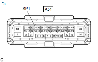
Front view of wire harness connector (to Skid Control ECU (Brake Actuator Assembly)) |
(a) Disconnect the A51 skid control ECU (brake actuator assembly) connector.
(b) Measure the voltage according to the value(s) in the table below.
Standard Voltage:
|
Tester Connection |
Condition |
Specified Condition |
|---|---|---|
|
A51-34 (SP1) - Body ground |
Ignition switch ON |
11 to 14 V |
| OK |
|
REPLACE SKID CONTROL ECU (BRAKE ACTUATOR ASSEMBLY) for Gasoline Model: Click here
for HV Model: Click here
|
|
|
26. |
CHECK HARNESS AND CONNECTOR (SKID CONTROL ECU (BRAKE ACTUATOR ASSEMBLY) - COMBINATION METER ASSEMBLY) |
(a) Disconnect the A51 skid control ECU (brake actuator assembly) connector.
(b) Disconnect the I4 combination meter assembly connector.
(c) Measure the resistance according to the value(s) in the table below.
Standard Resistance:
|
Tester Connection |
Condition |
Specified Condition |
|---|---|---|
|
A51-34 (SP1) - I4-20 (SI) |
Always |
Below 1 Ω |
| OK |
|
REPLACE SKID CONTROL ECU (BRAKE ACTUATOR ASSEMBLY) for Gasoline Model: Click here
for HV Model: Click here
|
| NG |
|
REPAIR OR REPLACE HARNESS OR CONNECTOR |
|
27. |
INSPECT COMBINATION METER ASSEMBLY (OUTPUT VOLTAGE) |
|
*a |
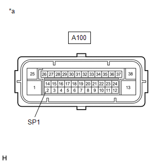
Front view of wire harness connector (to Skid Control ECU (Brake Actuator Assembly)) |
(a) Disconnect the A100 skid control ECU (brake actuator assembly) connector.
(b) Measure the voltage according to the value(s) in the table below.
Standard Voltage:
|
Tester Connection |
Condition |
Specified Condition |
|---|---|---|
|
A100-2 (SP1) - Body ground |
Ignition switch ON |
11 to 14 V |
| OK |
|
REPLACE SKID CONTROL ECU (BRAKE ACTUATOR ASSEMBLY) for Gasoline Model: Click here
for HV Model: Click here
|
|
|
28. |
CHECK HARNESS AND CONNECTOR (SKID CONTROL ECU (BRAKE ACTUATOR ASSEMBLY) - COMBINATION METER ASSEMBLY) |
(a) Disconnect the A51 skid control ECU (brake actuator assembly) connector.
(b) Disconnect the I4 combination meter assembly connector.
(c) Measure the resistance according to the value(s) in the table below.
Standard Resistance:
|
Tester Connection |
Condition |
Specified Condition |
|---|---|---|
|
A51-34 (SP1) - I4-20 (SI) |
Always |
Below 1 Ω |
| OK |
|
REPLACE SKID CONTROL ECU (BRAKE ACTUATOR ASSEMBLY) for Gasoline Model: Click here
for HV Model: Click here
|
| NG |
|
REPAIR OR REPLACE HARNESS OR CONNECTOR |
|
29. |
CONFIRM MODEL |
(a) Choose the model to be inspected.
|
Result |
Proceed to |
|---|---|
|
w/ Smart Key System |
A |
|
w/o Smart Key System with Electric Parking Brake System |
B |
|
w/o Smart Key System and Electric Parking Brake System |
C |
| B |
|
| C |
|
|
|
30. |
CHECK FOR DTC (SMART KEY SYSTEM (FOR START FUNCTION)) |
(a) Check for smart key system (for start function) DTCs are output.
Body Electrical > Power Source Control > Trouble Codes
|
Result |
Proceed to |
|---|---|
|
DTCs are not output |
A |
|
DTCs are output |
B |
| B |
|
GO TO SMART KEY SYSTEM (FOR START FUNCTION) for HV Model: Click here
for Gasoline Model: Click here
|
|
|
31. |
CHECK HARNESS AND CONNECTOR (CERTIFICATION ECU (SMART KEY ECU ASSEMBLY) - COMBINATION METER ASSEMBLY) |
(a) Disconnect the I1 certification ECU (smart key ECU assembly) connector.
(b) Disconnect the I4 combination meter assembly connector.
(c) Measure the resistance according to the value(s) in the table below.
Standard Resistance:
|
Tester Connection |
Condition |
Specified Condition |
|---|---|---|
|
I1-21 (SPDO) - I4-20 (SI) |
Always |
Below 1 Ω |
| OK |
|
| NG |
|
REPAIR OR REPLACE HARNESS OR CONNECTOR |
|
32. |
CHECK HARNESS AND CONNECTOR (SKID CONTROL ECU (BRAKE ACTUATOR ASSEMBLY) - COMBINATION METER ASSEMBLY) |
(a) Disconnect the A51 skid control ECU (brake actuator assembly) connector.
(b) Disconnect the I4 combination meter assembly connector.
(c) Measure the resistance according to the value(s) in the table below.
Standard Resistance:
|
Tester Connection |
Condition |
Specified Condition |
|---|---|---|
|
A51-34 (SP1) - I4-20 (SI) |
Always |
Below 1 Ω |
| OK |
|
REPLACE SKID CONTROL ECU (BRAKE ACTUATOR ASSEMBLY) for Gasoline Model: Click here
for HV Model: Click here
|
| NG |
|
REPAIR OR REPLACE HARNESS OR CONNECTOR |
|
33. |
CHECK HARNESS AND CONNECTOR (SKID CONTROL ECU (BRAKE ACTUATOR ASSEMBLY) - COMBINATION METER ASSEMBLY) |
(a) Disconnect the A100 skid control ECU (brake actuator assembly) connector.
(b) Disconnect the I4 combination meter assembly connector.
(c) Measure the resistance according to the value(s) in the table below.
Standard Resistance:
|
Tester Connection |
Condition |
Specified Condition |
|---|---|---|
|
A100-2 (SP1) - I4-20 (SI) |
Always |
Below 1 Ω |
| OK |
|
REPLACE SKID CONTROL ECU (BRAKE ACTUATOR ASSEMBLY) for Gasoline Model: Click here
for HV Model: Click here
|
| NG |
|
REPAIR OR REPLACE HARNESS OR CONNECTOR |
|
|
|