- DTC judgment completed
- System normal
| Last Modified: 07-31-2024 | 6.11:8.1.0 | Doc ID: RM10000000255XB |
| Model Year Start: 2023 | Model: GR Corolla | Prod Date Range: [09/2022 - ] |
| Title: G16E-GTS (ENGINE CONTROL): SFI SYSTEM: P071512,P071514; Input/Turbine Speed Sensor "A" Circuit Short to Battery; 2023 - 2025 MY GR Corolla [09/2022 - ] | ||
|
DTC |
P071512 |
Input/Turbine Speed Sensor "A" Circuit Short to Battery |
|
DTC |
P071514 |
Input/Turbine Speed Sensor "A" Circuit Short to Ground or Open |
DESCRIPTION
HINT:
In this troubleshooting procedure Input/Turbine Speed Sensor may be used in place of Input Speed Sensor (transmission revolution sensor).
The transmission revolution sensor system uses a gear attached to the input shaft and a Hall IC type sensor.
The Hall IC built into the transmission revolution sensor detects the change in magnetic flux density caused by the rotation of the input shaft gear and outputs a voltage signal representing the input shaft speed to the ECM.
|
DTC No. |
Detection Item |
DTC Detection Condition |
Trouble Area |
MIL |
Note |
|---|---|---|---|---|---|
|
P071512 |
Input/Turbine Speed Sensor "A" Circuit Short to Battery |
The transmission revolution sensor output voltage is higher than 1.8 V for 5 seconds or more (1 trip detection logic). |
|
Does not come on |
SAE Code: P07C0 |
|
P071514 |
Input/Turbine Speed Sensor "A" Circuit Short to Ground or Open |
The transmission revolution sensor output voltage is less than 0.2 V for 5 seconds or more (1 trip detection logic). |
|
Does not come on |
SAE Code: P07BF |
-
Reference: Inspection using an oscilloscope.
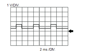
HINT:
The correct waveform is as shown.
ECM Terminal Name
Between NIMO and E1
Tester Range
1 V/DIV., 2 ms./DIV.
Condition
Engine idling and clutch pedal fully released
MONITOR DESCRIPTION
When the ignition switch to ON and the transmission revolution sensor output voltage is less than 0.2 V or higher than 1.8 V for 5 seconds or more, the ECM stores a DTC and illuminates the MIL.
CONFIRMATION DRIVING PATTERN
- Connect the GTS to the DLC3.
- Turn the ignition switch to ON.
- Turn the GTS on.
- Clear the DTCs (even if no DTCs are stored, perform the clear DTC procedure).
- Turn the ignition switch off and wait for at least 30 seconds.
- Turn the ignition switch to ON.
- Turn the GTS on.
- Wait 10 seconds or more.
- Enter the following menus: Powertrain / Engine / Trouble Codes.
-
Read the pending DTCs.
HINT:
- If a pending DTC is output, the system is malfunctioning.
- If a pending DTC is not output, perform the following procedure.
- Enter the following menus: Powertrain / Engine / Utility / All Readiness.
- Input the DTC: P071512 or P071514.
-
Check the DTC judgment result.
GTS Display
Description
NORMAL
ABNORMAL
- DTC judgment completed
- System abnormal
INCOMPLETE
- DTC judgment not completed
- Perform driving pattern after confirming DTC enabling conditions
HINT:
- If the judgment result is NORMAL, the system is normal.
- If the judgment result is ABNORMAL, the system is malfunctioning.
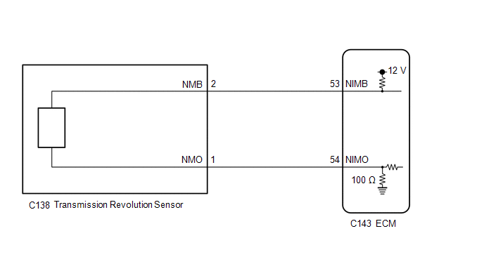
WIRING DIAGRAM
CAUTION / NOTICE / HINT
HINT:
Read Freeze Frame Data using the GTS. The ECM records vehicle and driving condition information as Freeze Frame Data the moment a DTC is stored. When troubleshooting, Freeze Frame Data can help determine if the vehicle was moving or stationary, if the engine was warmed up or not, if the air fuel ratio was lean or rich, and other data from the time the malfunction occurred.
PROCEDURE
|
1. |
READ VALUE USING GTS (NIM SENSOR SPEED) |
(a) Connect the GTS to the DLC3.
(b) Turn the ignition switch to ON.
(c) Turn the GTS on.
(d) Enter the following menus: Powertrain / Engine / Data List / Engine Speed and NIM Sensor Speed.
Powertrain > Engine > Data List
|
Tester Display |
|---|
|
Engine Speed |
|
NIM Sensor Speed |
(e) Start the engine.
(f) With the shift lever in neutral and the clutch pedal released, idle the engine and read the tester display.
Standard:
|
GTS Display |
Condition |
Specified Condition |
|---|---|---|
|
NIM Sensor Speed |
|
The value of the Data List item changes in accordance with the engine speed |
HINT:
- If the NIM sensor speed and engine speed match, the transmission revolution sensor is operating correctly.
- If the NIM sensor speed is 0 rpm even when the engine is running, it is possible that there is an open or short in the transmission revolution sensor circuit.
| OK |

|
|

|
2. |
CHECK HARNESS AND CONNECTOR |
|
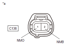
*a |
Front view of wire harness connector (to Transmission Revolution Sensor) |
HINT:
Make sure that the connector is properly connected. If it is not, securely connect it and check for DTCs again.
(a) Disconnect the transmission revolution sensor connector.
(b) Turn the ignition switch to ON.
(c) Measure the voltage according to the value(s) in the table below.
Standard Voltage:
|
Tester Connection |
Condition |
Specified Condition |
|---|---|---|
|
C138-2 (NMB) - Body ground |
Ignition switch ON |
11 to 14 V |
|
C138-1 (NMO) - Body ground |
Ignition switch ON |
Below 1 V |
(d) Turn the ignition switch off and wait for at least 30 seconds.
(e) Measure the resistance according to the value(s) in the table below.
Standard Resistance:
|
Tester Connection |
Condition |
Specified Condition |
|---|---|---|
|
C138-1 (NMO) - Body ground |
Ignition switch off |
95 to 105 Ω |
| OK |
|
|
|
3. |
CHECK HARNESS AND CONNECTOR (TRANSMISSION REVOLUTION SENSOR - ECM) |
(a) Disconnect the transmission revolution sensor connector.
(b) Disconnect the ECM connector.
(c) Measure the resistance according to the value(s) in the table below.
Standard Resistance:
|
Tester Connection |
Condition |
Specified Condition |
|---|---|---|
|
C138-2 (NMB) - C143-53 (NIMB) |
Always |
Below 1 Ω |
|
C138-1 (NMO) - C143-54 (NIMO) |
Always |
Below 1 Ω |
|
C138-2 (NMB) or C143-53 (NIMB) - Body ground and other terminals |
Always |
10 kΩ or higher |
|
C138-1 (NMO) or C143-54 (NIMO) - Body ground and other terminals |
Always |
10 kΩ or higher |
| OK |
|
REPLACE ECM
|
![2023 MY GR Corolla [09/2022 - 11/2022]; G16E-GTS (ENGINE CONTROL): ECM: REMOVAL](/t3Portal/stylegraphics/info.gif)
| NG |
|
REPAIR OR REPLACE HARNESS OR CONNECTOR |
|
|
|