| Last Modified: 05-13-2024 | 6.11:8.1.0 | Doc ID: RM10000000255VV |
| Model Year Start: 2023 | Model: GR Corolla | Prod Date Range: [09/2022 - ] |
| Title: G16E-GTS (ENGINE CONTROL): SFI SYSTEM: Lack of Power (Turbocharger System); 2023 - 2025 MY GR Corolla [09/2022 - ] | ||
|
Lack of Power (Turbocharger System) |
CAUTION / NOTICE / HINT
HINT:
- The diagnosis flowchart is for lack of power due to turbocharger factors.
- If symptom-specific diagnosis indicates a turbocharger related problem, check using this flowchart.
PROCEDURE
|
1. |
CHECK TURBOCHARGER SUB-ASSEMBLY |
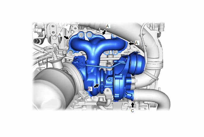
(a) Check for oil leaks and large carbon deposits around the connecting surfaces of the turbocharger sub-assembly.
HINT:
If oil leaks or a large amount of carbon deposits exist, air leaks from the respective sealing surfaces may be causing the lack of boost pressure.
|
Result |
Proceed to |
|---|---|
|
An oil leak or large amount of carbon deposits does not exist. |
A |
|
A large amount of carbon deposits exist around the turbine housing, flange or gaskets in any of the areas (A) shown in the illustration. |
B |
|
A large amount of carbon deposits exist around the waste gate valve link. |
C |
|
Oil is leaking from V-clamp in the area (B) shown in the illustration. |
D |
|
Oil is leaking from the compressor housing in any of the areas (C) shown in the illustration. |
E |
| B |

|
| C |
|
| D |
|
| E |
|
CHECK AND REPAIR AIR TUBE OR HOSE CLAMP |
|

|
2. |
CHECK TURBOCHARGER SUB-ASSEMBLY (INSPECT TURBINE SHAFT) |
(a) Check that the turbine shaft rotates smoothly, without catching.
(b) Check for loose turbine mounting nuts and for axial play in the turbine shaft.
Click here
![2023 - 2025 MY GR Corolla [09/2022 - ]; G16E-GTS (INTAKE / EXHAUST): TURBOCHARGER: INSPECTION](/t3Portal/stylegraphics/info.gif)
HINT:
If the turbine shaft catches or there is no play, seal failure due to seizure or improper operation due to accumulation of deposits is suspected.
|
Result |
Proceed to |
|---|---|
|
No turbine shaft malfunction |
A |
|
Turbine shaft malfunction |
B |
| B |
|
REPLACE TURBOCHARGER SUB-ASSEMBLY (TURBINE SHAFT MALFUNCTION) |
|
|
3. |
CHECK TURBOCHARGER SUB-ASSEMBLY (INSPECT WASTE GATE VALVE) |
(a) Use a vacuum pump to apply -35 +/-4.0 kPa (-263 +/-35 mmHg) negative pressure to the diaphragm chamber and check that the waste gate valve seats.
NOTICE:
Do not apply a negative pressure of -65 kPa (-488 mmHg) or more to the waste gate valve actuator with bracket assembly, as doing so may damage the diaphragm.
Standard:
Waste gate valve seats without a gap
|
Result |
Proceed to |
|---|---|
|
Seats at less than -35 kPa (-263 mmHg) negative pressure |
A |
|
Seats at -35 kPa (-263 mmHg) or greater negative pressure |
B |
|
Waste gate valve does not move |
C |
| B |
|
REPLACE TURBOCHARGER SUB-ASSEMBLY (WASTE GATE VALVE ACTUATOR MALFUNCTION) |
| C |
|
REPLACE TURBOCHARGER SUB-ASSEMBLY (WASTE GATE VALVE MALFUNCTION) |
|
|
4. |
CHECK TURBOCHARGER SUB-ASSEMBLY (INSPECT WASTE GATE VALVE) |
(a) Check for play in the waste gate valve and waste gate valve link.
Standard:
Play exists
HINT:
Some play is required as the waste gate valve link slides. If no play exists, the valve is determined to be stuck.
(b) Close the waste gate valve and using a feeler gauge, measure the clearance between the waste gate valve and the contact surface of the valve port of the turbine with valve housing sub-assembly waste gate.
Standard:
0.15 mm (0.0059 in.) or less
| NG |
|
REPLACE TURBOCHARGER SUB-ASSEMBLY (WASTE GATE VALVE MALFUNCTION) |
|
|
5. |
CHECK TURBOCHARGER SUB-ASSEMBLY (INSPECT AIR BY-PASS VALVE ASSEMBLY) |
(a) Inspect the air by-pass valve assembly.
Click here
| OK |
|
PROCEED TO NEXT SUSPECTED AREA SHOWN IN PROBLEM SYMPTOMS TABLE |
| NG |
|
REPLACE TURBOCHARGER SUB-ASSEMBLY (AIR BY-PASS VALVE ASSEMBLY MALFUNCTION) |
|
6. |
CHECK CYLINDER HEAD SUB-ASSEMBLY |
(a) Check for deformation or cracks in the mounting surfaces on the cylinder head sub-assy and the turbocharger sub-assembly.
HINT:
Deformation or cracks on a mounting surface may allow exhaust gas to leak from the damaged position.
Standard:
No deformation or cracks on a mounting surface
|
Result |
Proceed to |
|---|---|
|
No problem with the mounting surface |
A |
|
Deformation or cracks on the cylinder head sub-assy mounting surface |
B |
|
Deformation or cracks on the turbocharger sub-assembly mounting surface |
C |
| B |
|
| C |
|
|
|
7. |
REPLACE GASKET |
(a) Replace the gasket between the cylinder head sub-assy and turbocharger sub-assembly.
|
|
8. |
PERFORM SIMULATION TEST |
(a) Check that the abnormal state has disappeared.
| NEXT |
|
END |
|
9. |
CHECK TURBOCHARGER SUB-ASSEMBLY (INSPECT TURBINE HOUSING) |
(a) Check that the bushing of the turbine housing waste gate valve link is free of cracks.
(b) Close the waste gate valve and using a feeler gauge, measure the clearance between the waste gate valve and the contact surface of the valve port of the turbine with valve housing sub-assembly waste gate.
Standard:
No cracks and play does not exceed 0.15 mm (0.0059 in.)
| OK |
|
PROCEED TO NEXT SUSPECTED AREA SHOWN IN PROBLEM SYMPTOMS TABLE |
| NG |
|
REPLACE TURBOCHARGER SUB-ASSEMBLY (TURBINE HOUSING MALFUNCTION) |
|
|
|