| Last Modified: 05-13-2024 | 6.11:8.1.0 | Doc ID: RM100000001XA16 |
| Model Year Start: 2022 | Model: GR Corolla | Prod Date Range: [06/2021 - 09/2022] |
| Title: METER / GAUGE / DISPLAY: METER / GAUGE SYSTEM (for Gasoline Model): Fuel Receiver Gauge Malfunction; 2022 MY Corolla Corolla Hatchback GR Corolla [06/2021 - 09/2022] | ||
|
Fuel Receiver Gauge Malfunction |
DESCRIPTION
FUEL RECEIVER GAUGE OPERATION
(a) OPERATION
The combination meter assembly uses the fuel sender gauge assembly to detect the amount of fuel remaining in the fuel tank assembly. The Hall IC built into the fuel sender gauge assembly changes the output voltage according to the amount of fuel remaining. The combination meter assembly receives fuel consumption signals from the ECM and detects the voltage output from the fuel sender gauge assembly and operates the fuel receiver gauge.
FUEL RECEIVER GAUGE READING
(a) During normal driving:
While driving, the fuel level indicated by the fuel receiver gauge decreases according to the fuel consumed. As the fuel level in the fuel tank may be unstable depending on the driving conditions, the combination meter assembly corrects the fuel receiver gauge reading based on the fluctuations in the fuel level.
(b) During refueling:
When fuel is added to the fuel tank, if the fuel level increases by a certain amount or more, the output of the fuel sender gauge assembly will change. The combination meter assembly detects this change and determines that refueling has been performed and calculates the volume of fuel added. This is called refueling judgment. The combination meter assembly adjusts the fuel receiver gauge reading based on the refueling judgment.
NOTICE:
Add fuel with the ignition switch off to ensure safety and to enable refueling judgment so that an appropriate fuel receiver gauge reading will be obtained.
REFUELING JUDGMENT CONDITIONS
(a) Normal judgment condition (When normal refueling method is used)
With the ignition switch off, the fuel sender gauge assembly detects a change of 5.0 liters (5.3 US qts, 4.4 Imp. qts) or more in the fuel level.
(b) Other judgment conditions (When other refueling method is used)
With the ignition switch ON, the vehicle and engine stopped, the fuel sender gauge assembly detects a change of 5.0 liters (5.3 US qts, 4.4 Imp. qts) or more in the fuel level.
PRECAUTION FOR REFUELING
(a) The fuel sender gauge assembly cannot detect changes in the fuel level within certain ranges (around points E and F). Therefore, even if the refueling judgment conditions are satisfied, the fuel receiver gauge reading may not change when the fuel level is within either range.
(b) When refueling judgment is performed, it takes up to approximately 25 seconds for the fuel receiver gauge reading to change to the appropriate level.
FORCED RESET OF FUEL RECEIVER GAUGE
When refueling judgment conditions are not met, if the output of the fuel sender gauge assembly and the fuel receiver gauge reading differ by 15.0 liters (15.9 US qts, 13.2 Imp. qts) or more for approximately 5 minutes continuously, the fuel receiver gauge reading will reflect the detected fuel level without correction and it may take up to approximately 25 seconds for the reading to change to the appropriate level.
CAUTION / NOTICE / HINT
NOTICE:
When replacing the combination meter assembly, always replace it with a new one. If a combination meter assembly which was installed to another vehicle is used, the information stored in it will not match the information from the vehicle and a DTC may be stored.
HINT:
The fuel level warning light will come on when the fuel level is below 7.5 liters (7.9 US qts, 6.6 Imp. qts).
PROCEDURE
|
1. |
CONFIRM MODEL |
(a) Choose the model to be inspected.
|
Result |
Proceed to |
|---|---|
|
for M20A-FKS |
A |
|
for 2ZR-FAE |
B |
| B |

|
|

|
2. |
CHECK FOR DTC (SFI SYSTEM) |
(a) Check if SFI system DTCs are output.
Powertrain > Engine > Trouble Codes
|
Result |
Proceed to |
|---|---|
|
DTCs are not output |
A |
|
DTCs are output |
B |
| A |
|
| B |
|
|
3. |
CHECK FOR DTC (SFI SYSTEM) |
(a) Check if SFI system DTCs are output.
Powertrain > Engine and ECT > Trouble Codes
|
Result |
Proceed to |
|---|---|
|
DTCs are not output |
A |
|
DTCs are output |
B |
| B |
|
|
|
4. |
CHECK FOR DTC (ELECTRONICALLY CONTROLLED BRAKE SYSTEM) |
(a) Check if electronically controlled brake system DTCs are output.
Chassis > Brake > Trouble Codes
|
Result |
Proceed to |
|---|---|
|
DTCs are not output |
A |
|
DTCs are output |
B |
| B |
|
GO TO ELECTRONICALLY CONTROLLED BRAKE SYSTEM w/ Electric Parking Brake System: Click here
w/o Electric Parking Brake System: Click here
|
![2020 - 2022 MY Corolla Corolla Hatchback GR Corolla [03/2019 - 09/2022]; BRAKE CONTROL / DYNAMIC CONTROL SYSTEMS: ELECTRONICALLY CONTROLLED BRAKE SYSTEM (for Gasoline Model with Electric Parking Brake System): DIAGNOSTIC TROUBLE CODE CHART](/t3Portal/stylegraphics/info.gif)
|
|
5. |
CHECK FOR DTC (METER / GAUGE SYSTEM) |
(a) Check if meter / gauge system DTCs are output.
Body Electrical > Combination Meter > Trouble Codes
|
Result |
Proceed to |
|---|---|
|
DTC B150013 is not output |
A |
|
DTC B150013 is output |
B |
| B |
|
|
|
6. |
CHECK SYMPTOMS |
(a) Ask the customer about the problem symptoms.
|
Result |
Proceed to |
|---|---|
|
Malfunction occurs when adding fuel (Even after adding fuel, reading does not increase at all or increases very slowly, etc.) |
A |
|
Malfunction occurs during normal driving (The reading does not change, decreases quickly or decreases when the vehicle is not being driven, etc.) (The problem symptom recurs) |
B |
|
Malfunction occurs during normal driving (The reading does not change, decreases quickly or decreases when the vehicle is not being driven, etc.) (The problem symptom does not recur) |
C |
| B |
|
| C |
|
|
|
7. |
PERFORM ACTIVE TEST USING TECHSTREAM |
(a) Connect the Techstream to the DLC3.
(b) Turn the ignition switch ON.
(c) Turn the Techstream on.
(d) Enter following menus: Body Electrical / Combination Meter / Active Test.
(e) Perform the Active Test according to the display on the Techstream.
Body Electrical > Combination Meter > Active Test
|
Tester Display |
Measurement Item |
Control Range |
Diagnostic Note |
|---|---|---|---|
|
Fuel Gauge Operation (Sender E) |
Fuel receiver gauge (Sender E) |
ON |
See [Display 1] |
|
Fuel Gauge Operation (Empty) |
Fuel receiver gauge (Empty) |
ON |
See [Display 1] |
|
Fuel Gauge Operation (Warning) |
Fuel receiver gauge (Warning) |
ON |
See [Display 1] |
|
Fuel Gauge Operation (1/4) |
Fuel receiver gauge (1/4) |
ON |
See [Display 1] |
|
Fuel Gauge Operation (1/2) |
Fuel receiver gauge (1/2) |
ON |
See [Display 1] |
|
Fuel Gauge Operation (3/4) |
Fuel receiver gauge (3/4) |
ON |
See [Display 1] |
|
Fuel Gauge Operation (Full) |
Fuel receiver gauge (Full) |
ON |
See [Display 1] |
|
Fuel Gauge Operation (Sender F) |
Fuel receiver gauge (Sender F) |
ON |
See [Display 1] |
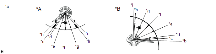
[Display 1]: Fuel Gauge Operation
|
*A |
for 4.2 Inch Type Multi-information Display |
*B |
for 7 Inch Type Multi-information Display |
|
*a |
Fuel Receiver Gauge |
*b |
Fuel Gauge Operation (Sender E) |
|
*c |
Fuel Gauge Operation (Empty) |
*d |
Fuel Gauge Operation (Warning) |
|
*e |
Fuel Gauge Operation (1/4) |
*f |
Fuel Gauge Operation (1/2) |
|
*g |
Fuel Gauge Operation (3/4) |
*h |
Fuel Gauge Operation (Full) |
|
*i |
Fuel Gauge Operation (Sender F) |
- |
- |
Body Electrical > Combination Meter > Active Test
|
Tester Display |
|---|
|
Fuel Gauge Operation (Sender E) |
Body Electrical > Combination Meter > Active Test
|
Tester Display |
|---|
|
Fuel Gauge Operation (Empty) |
Body Electrical > Combination Meter > Active Test
|
Tester Display |
|---|
|
Fuel Gauge Operation (Warning) |
Body Electrical > Combination Meter > Active Test
|
Tester Display |
|---|
|
Fuel Gauge Operation (1/4) |
Body Electrical > Combination Meter > Active Test
|
Tester Display |
|---|
|
Fuel Gauge Operation (1/2) |
Body Electrical > Combination Meter > Active Test
|
Tester Display |
|---|
|
Fuel Gauge Operation (3/4) |
Body Electrical > Combination Meter > Active Test
|
Tester Display |
|---|
|
Fuel Gauge Operation (Full) |
Body Electrical > Combination Meter > Active Test
|
Tester Display |
|---|
|
Fuel Gauge Operation (Sender F) |
OK:
Fuel receiver gauge indication is normal.
| NG |
|
|
|
8. |
CHECK FUEL RECEIVER GAUGE (OPERATION BY ADDING FUEL) |
(a) Record the fuel receiver gauge reading.
(b) If the fuel tank assembly is almost full, drain 20 liters (21.1 US qts, 17.6 Imp. qts) or more of fuel. (This is not necessary when the fuel tank assembly is sufficiently below full.)
(c) Disconnect the cable from the negative (-) battery terminal to reset the fuel receiver gauge.
NOTICE:
Make sure that the ignition switch is off before disconnecting the cable from the negative (-) battery terminal.
(d) Connect the cable to the negative (-) battery terminal and turn the ignition switch ON.
(e) Check that the fuel receiver gauge has been reset.
(f) Drive the vehicle at 1.8 km/h (1 mph) or more, then stop the vehicle and turn the ignition switch off.
(g) Add 5.0 liters (5.3 US qts, 4.4 Imp. qts) or more of fuel, turn the ignition switch to ON, and check that the fuel receiver gauge reading increases in proportion to the amount of fuel added.
|
Result |
Proceed to |
|---|---|
|
Fuel receiver gauge reading increases in proportion to the amount of fuel added |
A |
|
Fuel receiver gauge reading does not change even when fuel is added |
B |
| A |
|
| B |
|
|
9. |
PERFORM ACTIVE TEST USING TECHSTREAM |
(a) Connect the Techstream to the DLC3.
(b) Turn the ignition switch ON.
(c) Turn the Techstream on.
(d) Enter following menus: Body Electrical / Combination Meter / Active Test.
(e) Perform the Active Test according to the display on the Techstream.
Body Electrical > Combination Meter > Active Test
|
Tester Display |
Measurement Item |
Control Range |
Diagnostic Note |
|---|---|---|---|
|
Fuel Gauge Operation (Sender E) |
Fuel receiver gauge (Sender E) |
ON |
See [Display 1] |
|
Fuel Gauge Operation (Empty) |
Fuel receiver gauge (Empty) |
ON |
See [Display 1] |
|
Fuel Gauge Operation (Warning) |
Fuel receiver gauge (Warning) |
ON |
See [Display 1] |
|
Fuel Gauge Operation (1/4) |
Fuel receiver gauge (1/4) |
ON |
See [Display 1] |
|
Fuel Gauge Operation (1/2) |
Fuel receiver gauge (1/2) |
ON |
See [Display 1] |
|
Fuel Gauge Operation (3/4) |
Fuel receiver gauge (3/4) |
ON |
See [Display 1] |
|
Fuel Gauge Operation (Full) |
Fuel receiver gauge (Full) |
ON |
See [Display 1] |
|
Fuel Gauge Operation (Sender F) |
Fuel receiver gauge (Sender F) |
ON |
See [Display 1] |
[Display 1]: Fuel Gauge Operation
|
*A |
for 4.2 Inch Type Multi-information Display |
*B |
for 7 Inch Type Multi-information Display |
|
*a |
Fuel Receiver Gauge |
*b |
Fuel Gauge Operation (Sender E) |
|
*c |
Fuel Gauge Operation (Empty) |
*d |
Fuel Gauge Operation (Warning) |
|
*e |
Fuel Gauge Operation (1/4) |
*f |
Fuel Gauge Operation (1/2) |
|
*g |
Fuel Gauge Operation (3/4) |
*h |
Fuel Gauge Operation (Full) |
|
*i |
Fuel Gauge Operation (Sender F) |
- |
- |
Body Electrical > Combination Meter > Active Test
|
Tester Display |
|---|
|
Fuel Gauge Operation (Sender E) |
Body Electrical > Combination Meter > Active Test
|
Tester Display |
|---|
|
Fuel Gauge Operation (Empty) |
Body Electrical > Combination Meter > Active Test
|
Tester Display |
|---|
|
Fuel Gauge Operation (Warning) |
Body Electrical > Combination Meter > Active Test
|
Tester Display |
|---|
|
Fuel Gauge Operation (1/4) |
Body Electrical > Combination Meter > Active Test
|
Tester Display |
|---|
|
Fuel Gauge Operation (1/2) |
Body Electrical > Combination Meter > Active Test
|
Tester Display |
|---|
|
Fuel Gauge Operation (3/4) |
Body Electrical > Combination Meter > Active Test
|
Tester Display |
|---|
|
Fuel Gauge Operation (Full) |
Body Electrical > Combination Meter > Active Test
|
Tester Display |
|---|
|
Fuel Gauge Operation (Sender F) |
OK:
Fuel receiver gauge indication is normal.
| NG |
|
|
|
10. |
CHECK FUEL RECEIVER GAUGE |
(a) Disconnect the cable from the negative (-) battery terminal to reset the fuel receiver gauge.
NOTICE:
Make sure that the ignition switch is off before disconnecting the cable from the negative (-) battery terminal.
(b) Connect the cable to the negative (-) battery terminal and turn the ignition switch ON.
(c) Check if the fuel receiver gauge reading corresponds with the amount of fuel remaining in the fuel tank assembly.
|
Result |
Proceed to |
|---|---|
|
Fuel receiver gauge reading corresponds with the amount of fuel remaining in the fuel tank assembly |
A |
|
Fuel receiver gauge reading does not correspond with the amount of fuel remaining in the fuel tank assembly |
B |
| A |
|
END |
| B |
|
|
11. |
INSPECT FUEL TANK ASSEMBLY |
HINT:
Inspect the fuel tank assembly and fuel sender assembly for deformation, foreign matter or an improperly installed fuel receiver gauge, as this may be the cause of the fuel receiver gauge malfunction.
(a) Visually check the fuel tank assembly for any abnormalities.
(b) Check if there is an excessive amount of foreign matter in the fuel tank assembly.
(c) Visually check the fuel sender gauge assembly for damage and confirm that it operates correctly.
(d) Check the installation condition of the fuel tank assembly and fuel sender gauge assembly.
|
Result |
Proceed to |
|---|---|
|
Normal |
A |
|
Appearance of the fuel tank assembly is abnormal |
B |
|
There is an excessive amount of foreign matter in the fuel tank assembly |
C |
|
The fuel sender gauge assembly is visually damaged or does not operate correctly |
D |
|
The fuel tank assembly or fuel sender gauge assembly is not installed correctly |
E |
| A |
|
| B |
|
REPLACE FUEL TANK ASSEMBLY for M20A-FKS (w/ Canister Pump Module): Click here
for M20A-FKS (w/o Canister Pump Module): Click here
for 2ZR-FAE (w/ canister pump module): Click here
for 2ZR-FAE (w/o canister pump module): Click here
|
| C |
|
CLEAN INSIDE OF FUEL TANK ASSEMBLY |
| D |
|
REPLACE FUEL SENDER GAUGE ASSEMBLY for M20A-FKS (w/ Canister Pump Module): Click here
for M20A-FKS (w/o Canister Pump Module): Click here
for 2ZR-FAE (w/ canister pump module): Click here
for 2ZR-FAE (w/o canister pump module): Click here
|
| E |
|
INSTALL FUEL TANK ASSEMBLY OR FUEL SENDER GAUGE ASSEMBLY CORRECTLY |
|
|
|