- Replacement of cam timing control motor with EDU assembly
- Removal and installation of a cam timing control motor with EDU assembly
| Last Modified: 05-13-2024 | 6.11:8.1.0 | Doc ID: RM100000001WMZA |
| Model Year Start: 2022 | Model: Corolla Hatchback | Prod Date Range: [06/2021 - 09/2022] |
| Title: M20A-FKS (ENGINE CONTROL): CAMSHAFT TIMING CONTROL MOTOR: REMOVAL; 2022 MY Corolla Corolla Hatchback [06/2021 - 09/2022] | ||
REMOVAL
CAUTION / NOTICE / HINT
The necessary procedures (adjustment, calibration, initialization or registration) that must be performed after parts are removed and installed, or replaced during cam timing control motor with EDU assembly removal/installation are shown below.
Necessary Procedures After Parts Removed/Installed/Replaced
|
Replaced Part or Performed Procedure |
Necessary Procedure |
Effect/Inoperative Function when Necessary Procedure not Performed |
Link |
|---|---|---|---|
|
*1: for Hatchback
*2: w/ Smart Key System *3: w/o Smart Key System |
|||
|
Battery terminal is disconnected/reconnected |
Perform steering sensor zero point calibration |
Lane Control System (for Gasoline Model) |
|
|
Pre-collision System (for Gasoline Model) |
|||
|
Lighting System (w/ AFS)(EXT) |
|||
|
Initialize back door lock*1 |
Power Door Lock Control System (for Hatchback, Gasoline Model) |
||
|
|
Inspection after repair |
|
|
|
Replacement of ECM |
Vehicle Identification Number (VIN) registration |
MIL comes on |
|
|
ECU communication ID registration (Immobiliser system) |
Engine start function |
||
|
|
||
|
Replacement of ECM*2 |
Code registration (Smart Key System (for Gasoline Model, Start Function)) |
|
|
|
Replacement of ECM*3 |
Code registration (Immobiliser system) |
Engine start |
|
NOTICE:
- After the ignition switch is turned off, the radio and display receiver assembly records various types of memory and settings. As a result, after turning the ignition switch off, make sure to wait at least 85 seconds before disconnecting the cable from the negative (-) battery terminal. (for Navigation System and Audio and Visual System (for Gasoline Model))
- This procedure includes the removal of small-head bolts. Refer to Small-Head Bolts of Basic Repair Hint to identify the small-head bolts.
PROCEDURE
1. REMOVE NO. 1 ENGINE UNDER COVER ASSEMBLY
2. REMOVE REAR ENGINE UNDER COVER RH
3. REMOVE WINDSHIELD WIPER MOTOR AND LINK ASSEMBLY
4. REMOVE NO. 1 HEATER AIR DUCT SPLASH SHIELD SEAL
5. REMOVE OUTER COWL TOP PANEL SUB-ASSEMBLY
6. REMOVE ECM
7. REMOVE BATTERY
8. REMOVE BATTERY CLAMP SUB-ASSEMBLY
9. REMOVE FUEL DELIVERY GUARD
10. INSTALL ENGINE HANGER
11. INSTALL ENGINE SUPPORT BRIDGE
12. REMOVE ENGINE MOUNTING INSULATOR SUB-ASSEMBLY RH
|
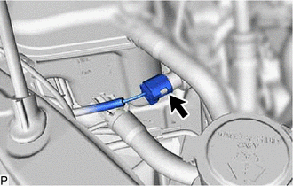
(a) Disconnect the air conditioner pressure sensor connector. |
|
|
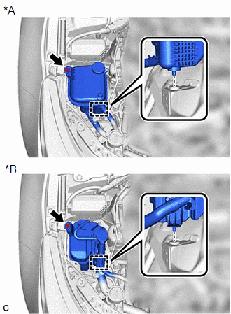
(b) Remove the bolt. |
|
(c) Disengage the pin and separate the reserve sealed tank.
|
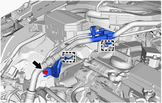
(d) Remove the bolt and disengage the clamp to remove the No. 1 cooler refrigerant hose bracket from the engine mounting insulator sub-assembly RH. |
|
(e) Disengage the clamp to separate the piping clamp.
|
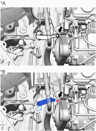
(f) Remove the bolt and separate the No. 2 earth wire from the engine mounting insulator sub-assembly RH. |
|
|
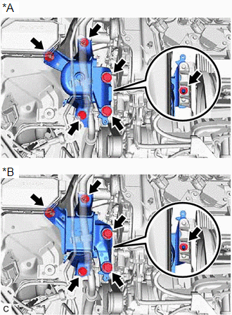
(g) Remove the 4 bolts, 2 nuts and engine mounting insulator sub-assembly RH from the vehicle body and engine mounting bracket RH. HINT: As the engine mounting insulator sub-assembly RH contacts the air conditioning tube assembly and cannot be taken out, move the engine mounting insulator sub-assembly RH to a position where the bolt of the cam timing control motor with EDU assembly can be removed. |
|
13. REMOVE CAM TIMING CONTROL MOTOR WITH EDU ASSEMBLY
|
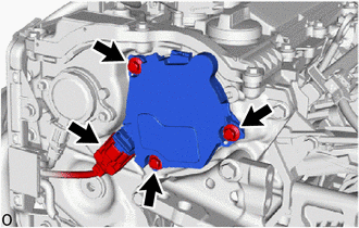
(a) Disconnect the cam timing control motor with EDU assembly connector. |
|
(b) Remove the 3 bolts and cam timing control motor with EDU assembly from the No. 2 timing chain cover assembly.
NOTICE:
If the cam timing control motor with EDU assembly has been struck or dropped, replace it.
14. REMOVE CAM TIMING CONTROL MOTOR O-RING
|
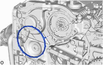
(a) Remove the cam timing control motor O-ring from the No. 2 timing chain cover assembly. |
|
|
|
|
![2019 - 2022 MY Corolla Corolla Hatchback GR Corolla [06/2018 - 09/2022]; PRE-COLLISION: PRE-COLLISION SYSTEM (for Gasoline Model): INITIALIZATION](/t3Portal/stylegraphics/info.gif)
