- Shift Position
- Shift Position Sensor (PNB)
- Shift Position Sensor (PR)
- Shift Position Sensor (DB1)
- Shift Position Sensor (DB2)
- Shift Position Sensor (N)
- Shift Position Sensor (R)
- Shift Position Sensor (P)
| Last Modified: 01-27-2025 | 6.11:8.1.0 | Doc ID: RM100000001N3YF |
| Model Year Start: 2021 | Model: Corolla | Prod Date Range: [04/2020 - 09/2022] |
| Title: HYBRID / BATTERY CONTROL: HYBRID CONTROL SYSTEM (for LITHIUM-ION BATTERY with P610): P070562; Transmission Range Sensor "A" Circuit (PRNDL Input) Signal Compare Failure; 2021 - 2022 MY Corolla Corolla HV [04/2020 - 09/2022] | ||
|
DTC |
P070562 |
Transmission Range Sensor "A" Circuit (PRNDL Input) Signal Compare Failure |
DESCRIPTION
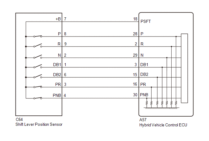
The shift lever position sensor sends 7 different switch signals to the hybrid vehicle control ECU. The hybrid vehicle control ECU uses these signals to detect the shift lever position (P, R, N, D or B). The hybrid vehicle control ECU also uses this information to determine the intended direction of travel (forward or reverse).
|
DTC No. |
Detection Item |
DTC Detection Condition |
Trouble Area |
MIL |
Warning Indicate |
|---|---|---|---|---|---|
|
P070562 |
Transmission Range Sensor "A" Circuit (PRNDL Input) Signal Compare Failure |
Shift sensor circuit malfunction (abnormal pattern) A malfunction in the P, R, N, D or B circuit is detected based on the shift sensor input pattern. (1 trip detection logic) |
|
Does not come on |
Master Warning: Comes on |
Related Data List
|
DTC No. |
Data List |
|---|---|
|
P070562 |
|
CONFIRMATION DRIVING PATTERN
HINT:
After repair has been completed, clear the DTCs and then check that the vehicle has returned to normal by performing the following All Readiness check procedure.
Click here
![2021 - 2022 MY Corolla Corolla HV [04/2020 - 09/2022]; HYBRID / BATTERY CONTROL: HYBRID CONTROL SYSTEM (for LITHIUM-ION BATTERY with P610): UTILITY](/t3Portal/stylegraphics/info.gif)
- Connect the Techstream to the DLC3.
- Turn the power switch on (IG) and turn the Techstream on.
- Clear the DTCs (even if no DTCs are stored, perform the clear DTC procedure).
- Turn the power switch off and wait for 2 minutes or more.
- Turn the power switch on (IG) and turn the Techstream on.
- Slowly move the shift lever from P to B then back to P.
- Enter the following menus: Powertrain / Hybrid Control / Utility / All Readiness.
-
Check the DTC judgment result.
HINT:
- If the judgment result shows NORMAL, the system is normal.
- If the judgment result shows ABNORMAL, the system has a malfunction.
- If the judgment result shows INCOMPLETE or N/A, perform driving pattern again.
WIRING DIAGRAM
PROCEDURE
|
1. |
READ VALUE USING TECHSTREAM (SHIFT POSITION SENSOR) |
(a) Connect the Techstream to the DLC3.
(b) Turn the power switch on (IG).
(c) Enter the following menus: Powertrain / Hybrid Control / Data List / Shift Position Sensor (PNB), Shift Position Sensor (PR), Shift Position Sensor (DB1), Shift Position Sensor (DB2), Shift Position Sensor (N), Shift Position Sensor (R), Shift Position Sensor (P).
Powertrain > Hybrid Control > Data List
|
Tester Display |
|---|
|
Shift Position Sensor (PNB) |
|
Shift Position Sensor (PR) |
|
Shift Position Sensor (DB1) |
|
Shift Position Sensor (DB2) |
|
Shift Position Sensor (N) |
|
Shift Position Sensor (R) |
|
Shift Position Sensor (P) |
(d) While slowly moving the shift lever from P to B, then back to P, read the Data List (Shift Position Sensor) displayed on the Techstream.
HINT:
Be sure to move the shift lever slowly.
Standard:
|
Data List |
Shift Position |
||||
|
P |
R |
N |
D |
B |
|
|
Shift Position Sensor (P) |
ON |
OFF |
OFF |
OFF |
OFF |
|
Shift Position Sensor (R) |
OFF |
ON |
OFF |
OFF |
OFF |
|
Shift Position Sensor (PR) |
ON |
ON |
OFF |
OFF |
OFF |
|
Shift Position Sensor (N) |
OFF |
OFF |
ON |
OFF |
OFF |
|
Shift Position Sensor (DB1) |
OFF |
OFF |
OFF |
ON |
ON |
|
Shift Position Sensor (DB2) |
OFF |
OFF |
OFF |
ON |
ON |
|
Shift Position Sensor (PNB) |
ON |
OFF |
ON |
OFF |
ON |
(e) Check for DTCs.
Powertrain > Hybrid Control > Trouble Codes
OK:
DTC P070562 is not output.
(f) Turn the power switch off.
| NG |

|
|

|
2. |
CHECK FOR INTERMITTENT PROBLEMS |
Click here
| OK |
|
| NG |
|
REPAIR OR REPLACE MALFUNCTIONING PARTS, COMPONENT AND AREA |
|
3. |
INSPECT SHIFT LEVER POSITION SENSOR |
(a) Turn the power switch on (IG).
(b) Measure the voltage according to the value(s) in the table below.
|
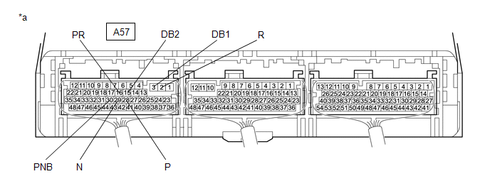
*a |
Component with harness connected (Hybrid Vehicle Control ECU) |
- |
- |
Standard Voltage:
|
Tester Connection |
Condition |
Specified Condition |
|---|---|---|
|
A57-28 (P) - Body ground |
Power switch on (IG) Shift lever in P |
7.5 to 14 V |
|
Power switch on (IG) Shift lever in any position except P |
0 to 1.5 V |
|
|
A57-2 (R) - Body ground |
Power switch on (IG) Shift lever in R |
7.5 to 14 V |
|
Power switch on (IG) Shift lever in any position except R |
0 to 1.5 V |
|
|
A57-16 (PR) - Body ground |
Power switch on (IG) Shift lever in P or R |
7.5 to 14 V |
|
Power switch on (IG) Shift lever in any position except P or R |
0 to 1.5 V |
|
|
A57-29 (N) - Body ground |
Power switch on (IG) Shift lever in N |
7.5 to 14 V |
|
Power switch on (IG) Shift lever in any position except N |
0 to 1.5 V |
|
|
A57-3 (DB1) - Body ground |
Power switch on (IG) Shift lever in D or B |
7.5 to 14 V |
|
Power switch on (IG) Shift lever in any position except D or B |
0 to 1.5 V |
|
|
A57-15 (DB2) - Body ground |
Power switch on (IG) Shift lever in D or B |
7.5 to 14 V |
|
Power switch on (IG) Shift lever in any position except D or B |
0 to 1.5 V |
|
|
A57-30 (PNB) - Body ground |
Power switch on (IG) Shift lever in P, N or B |
7.5 to 14 V |
|
Power switch on (IG) Shift lever in any position except P, N or B |
0 to 1.5 V |
(c) Turn the power switch off.
| OK |
|
|
|
4. |
CHECK HARNESS AND CONNECTOR (POWER SOURCE CIRCUIT) |
|
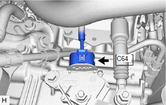
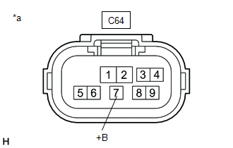
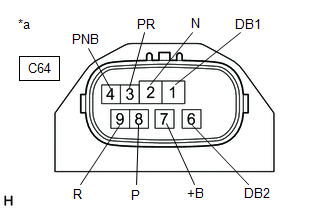
(a) Disconnect the C64 shift lever position sensor connector. Click here
|
|
(b) Turn the power switch on (IG).
|
(c) Measure the voltage according to the value(s) in the table below. Standard Voltage:
NOTICE: Turning the power switch on (IG) with the shift lever position sensor connector disconnected causes other DTCs to be stored. Clear the DTCs after performing this inspection. |
|
(d) Turn the power switch off.
(e) Reconnect the C64 shift lever position sensor connector.
| NG |
|
|
|
5. |
INSPECT SHIFT LEVER POSITION SENSOR |
|
(a) Disconnect the C64 shift lever position sensor connector. |
|
|
(b) Measure the resistance according to the value(s) in the table below. Standard Resistance:
HINT: Terminal No. 5 on the component side connector is empty. |
|
(c) Reconnect the C64 shift lever position sensor connector.
| OK |
|
REPAIR OR REPLACE HARNESS OR CONNECTOR |
| NG |
|
|
6. |
CHECK HARNESS AND CONNECTOR (SHIFT LEVER POSITION SENSOR - HYBRID VEHICLE CONTROL ECU) |
(a) Disconnect the C64 shift lever position sensor connector.
(b) Disconnect the A57 hybrid vehicle control ECU connector.
|
(c) Measure the resistance according to the value(s) in the table below. Standard Resistance:
|
|
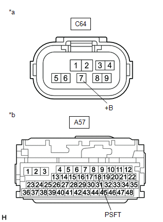
(d) Reconnect the A57 hybrid vehicle control ECU connector.
(e) Reconnect the C64 shift lever position sensor connector.
| OK |
|
| NG |
|
REPAIR OR REPLACE HARNESS OR CONNECTOR |
|
|
|