| Last Modified: 05-13-2024 | 6.11:8.1.0 | Doc ID: RM100000001N34U |
| Model Year Start: 2021 | Model: Corolla | Prod Date Range: [04/2020 - 09/2022] |
| Title: HYBRID / BATTERY CONTROL: HYBRID BATTERY SYSTEM (for LITHIUM-ION BATTERY with P610): P0E2D00; Hybrid/EV Battery Energy Control Module Hybrid/EV Battery Monitor Performance; 2021 - 2022 MY Corolla Corolla HV [04/2020 - 09/2022] | ||
|
DTC |
P0E2D00 |
Hybrid/EV Battery Energy Control Module Hybrid/EV Battery Monitor Performance |
DESCRIPTION
The battery ECU assembly detects the voltage of each HV battery cell. The battery ECU assembly monitors its internal HV battery cell voltage detection circuits to detect malfunctions. If the battery ECU assembly detects a malfunction it will store this DTC.
HINT:
If this DTC is output, it will be necessary to replace the battery ECU assembly.
|
DTC No. |
Detection Item |
DTC Detection Condition |
Trouble Area |
MIL |
Warning Indicate |
|---|---|---|---|---|---|
|
P0E2D00 |
Hybrid/EV Battery Energy Control Module Hybrid/EV Battery Monitor Performance |
The battery ECU assembly detects a malfunction of its internal HV battery cell voltage detection circuits. (1 trip detection logic) |
|
Comes on |
Master Warning: Comes on |
Related Data List
|
DTC No. |
Data List |
|---|---|
|
P0E2D00 |
Hybrid/EV Battery Cell 1 to 56 Voltage |
MONITOR DESCRIPTION
The battery ECU assembly monitors its internal HV battery cell voltage detection circuits to detect malfunctions. If the battery ECU assembly detects a malfunction, it will illuminate the MIL and store a DTC.
MONITOR STRATEGY
|
Related DTCs |
P0E2D (INF P0E2D00): Internal control module hybrid/EV battery monitor performance |
|
Required sensors/components |
Battery ECU assembly |
|
Frequency of operation |
Continuous |
|
Duration |
TMC's intellectual property |
|
MIL operation |
1 driving cycle |
|
Sequence of operation |
None |
TYPICAL ENABLING CONDITIONS
|
The monitor will run whenever the following DTCs are not stored |
TMC's intellectual property |
|
Other conditions belong to TMC's intellectual property |
- |
TYPICAL MALFUNCTION THRESHOLDS
|
TMC's intellectual property |
- |
COMPONENT OPERATING RANGE
|
Battery ECU assembly |
DTC P0E2D (INF P0E2D00) is not detected |
CONFIRMATION DRIVING PATTERN
HINT:
After repair has been completed, clear the DTC and then check that the vehicle has returned to normal by performing the following All Readiness check procedure.
HINT:
-
After repair has been completed, clear the DTC and then check that the vehicle has returned to normal by performing the following All Readiness check procedure.
Click here
![2021 - 2022 MY Corolla Corolla HV [04/2020 - 09/2022]; HYBRID / BATTERY CONTROL: HYBRID BATTERY SYSTEM (for LITHIUM-ION BATTERY with P610): UTILITY](/t3Portal/stylegraphics/info.gif)
-
When clearing the permanent DTCs, refer to the "CLEAR PERMANENT DTC" procedure.
Click here
- Connect the Techstream to the DLC3.
- Turn the power switch on (IG) and turn the Techstream on.
- Clear the DTCs (even if no DTCs are stored, perform the clear DTC procedure).
- Turn the power switch off and wait for 2 minutes or more.
- Turn the power switch on (IG) and turn the Techstream on.
- With the vehicle stopped and the shift position in P, turn the power switch on (IG) and wait for at least 70 seconds. [*1]
- Turn the power switch on (READY) and without depressing the accelerator pedal, and while depressing the brake pedal, change the shift position to D and wait for 1 minutes. (Step A)[*2]
- Drive the vehicle 0.5 m (1.6 ft.) forward and perform step A.[*3]
-
Drive the vehicle another 0.5 m (1.6 ft.) forward and perform step A. Repeat this procedure 5 times (minimum total driving distance: 2 m (6.6 ft.)).[*4]
HINT:
[*1] to [*4]: Normal judgment procedure.
The normal judgment procedure is used to complete DTC judgment and also used when clearing permanent DTCs.
- Enter the following menus: Powertrain / HV Battery / Utility / All Readiness.
-
Check the DTC judgment result.
HINT:
- If the judgment result shows NORMAL, the system is normal.
- If the judgment result shows ABNORMAL, the system has a malfunction.
- If the judgment result shows INCOMPLETE or N/A, perform the normal judgment procedure again.
WIRING DIAGRAM
Refer to the wiring diagram for DTC P1A001C.
Click here
CAUTION / NOTICE / HINT
CAUTION:
-
Before the following operations are conducted, take precautions to prevent electric shock by turning the power switch off, wearing insulated gloves, and removing the service plug grip from HV battery.
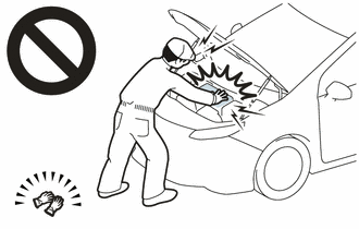
- Inspecting the high-voltage system
- Disconnecting the low voltage connector of the inverter with converter assembly
- Disconnecting the low voltage connector of the HV battery
-
To prevent electric shock, make sure to remove the service plug grip to cut off the high voltage circuit before servicing the vehicle.
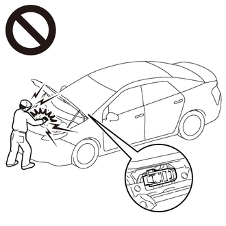
-
After removing the service plug grip from the HV battery, put it in your pocket to prevent other technicians from accidentally reconnecting it while you are working on the high-voltage system.
-
After removing the service plug grip, wait for at least 10 minutes before touching any of the high-voltage connectors or terminals. After waiting for 10 minutes, check the voltage at the terminals in the inspection point in the inverter with converter assembly. The voltage should be 0 V before beginning work.
Click here
HINT:
Waiting for at least 10 minutes is required to discharge the high-voltage capacitor inside the inverter with converter assembly.
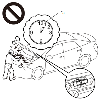
*a
Without waiting for 10 minutes
-
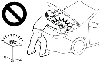
Make sure to insulate the high-voltage connectors and terminals of the HV battery with insulating tape after removing it.
If the HV battery stored without insulating the connectors and terminals, electric shock or fire may result.
-
When disposing of an HV battery, make sure to return it through an authorized collection agent who is capable of handling it safely. If the HV battery is returned via the manufacturer specified route, it will be returned properly and in a safe manner by an authorized collection agent.
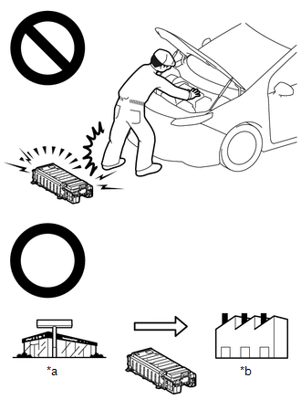
*a
Dealer
*b
Battery Collection Agent
- Accidents such as electric shock may result if the HV battery is disposed of improperly or abandoned. Therefore, make sure to return all HV batteries through an authorized collection agent.
-
Before returning the HV battery, make sure to perform a recovery inspection.
Click here
-
Before returning the HV supply stack sub-assembly, make sure to perform a recovery inspection.
Click here
- Make a note of the output DTCs as some of them may be necessary for recovery inspection of the HV battery and HV supply stack sub-assemblies.
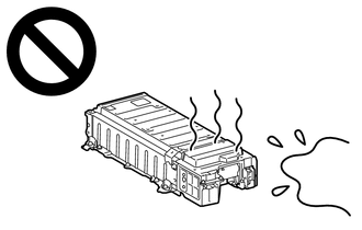
-
After removing the HV battery, keep it away from water. Exposure to water may cause the HV battery to produce heat, resulting in a fire.
NOTICE:
After turning the power switch off, waiting time may be required before disconnecting the cable from the negative (-) auxiliary battery terminal. Therefore, make sure to read the disconnecting the cable from the negative (-) auxiliary battery terminal notices before proceeding with work.
Click here
HINT:
P0E2D00 may be output as a result of the malfunction indicated by the DTCs in table below.
- The chart above is listed in inspection order of priority.
- Check DTCs that are output at the same time by following the listed order. (The main cause of the malfunction can be determined without performing unnecessary inspections.)
|
Malfunction Content |
Relevant DTC |
|
|---|---|---|
|
Microcomputer malfunction |
P0A1F94 |
Hybrid/EV Battery Energy Control Module Unexpected Operation |
|
P062F46 |
Hybrid/EV Battery Energy Control Module EEPROM Calibration / Parameter Memory Failure |
|
|
P0A1D94 |
Hybrid/EV Powertrain Control Module Unexpected Operation |
|
|
P060A47 |
Hybrid/EV Battery Energy Control Module Monitoring Processor Watchdog / Safety MCU Failure |
|
|
P060B49 |
Hybrid/EV Battery Energy Control Module A/D Processing Internal Electronic Failure |
|
|
P060687 |
Hybrid/EV Battery Energy Control Module Processor to Monitoring Processor Missing Message |
|
|
P060A87 |
Hybrid/EV Battery Energy Control Module Processor from Monitoring Processor Missing Message |
|
|
P060629 |
Hybrid/EV Battery Energy Control Module Processor to Monitoring Processor Signal Invalid |
|
|
U029387 |
Lost Communication with Hybrid/EV Powertrain Control Module Missing Message |
|
|
U010087 |
Lost Communication with ECM/PCM "A" Missing Message |
|
|
U115087 |
Lost Communication with Hybrid Powertrain Control Module (Hybrid/EV Battery Local Bus) Missing Message |
|
|
P056014 |
System Voltage (BATT) Circuit Short to Ground or Open |
|
|
P0ABF00 |
Hybrid/EV Battery Current Sensor "A" Circuit Range/Performance |
|
PROCEDURE
|
1. |
CHECK DTC OUTPUT (HV BATTERY) |
(a) Connect the Techstream to the DLC3.
(b) Turn the power switch on (IG).
(c) Enter the following menus: Powertrain / HV Battery / Trouble Codes.
(d) Check for DTCs.
Powertrain > HV Battery > Trouble Codes
|
Result |
Proceed to |
|---|---|
|
"P0E2D00" only is output, or DTCs except the ones in the table below are also output. |
A |
|
DTCs of hybrid battery system in the table below are output. |
B |
|
System |
Relevant DTC |
|
|---|---|---|
|
Hybrid battery system |
P1A001C |
Hybrid Battery Stack 2 Cell Voltage Detection Voltage Out of Range |
|
P1A051C |
Hybrid Battery Stack 3 Cell Voltage Detection Voltage Out of Range |
|
|
P1A0A1C |
Hybrid Battery Stack 4 Cell Voltage Detection Voltage Out of Range |
|
|
P1AC413 |
Hybrid/EV Battery Stack 1 Current Interrupt Device Circuit Open |
|
|
P1AC49E |
Hybrid/EV Battery Stack 1 Current Interrupt Device Stuck On |
|
|
P1AC513 |
Hybrid/EV Battery Stack 2 Current Interrupt Device Circuit Open |
|
|
P1AC59E |
Hybrid/EV Battery Stack 2 Current Interrupt Device Stuck On |
|
|
P1AC613 |
Hybrid/EV Battery Stack 3 Current Interrupt Device Circuit Open |
|
|
P1AC69E |
Hybrid/EV Battery Stack 3 Current Interrupt Device Stuck On |
|
|
P1AC713 |
Hybrid/EV Battery Stack 4 Current Interrupt Device Circuit Open |
|
|
P1AC79E |
Hybrid/EV Battery Stack 4 Current Interrupt Device Stuck On |
|
|
P301A1C |
Hybrid Battery Stack 1 Cell Voltage Detection Voltage Out of Range |
|
(e) Turn the power switch off.
| B |

|
|

|
2. |
CHECK CONNECTOR CONNECTION CONDITION (BATTERY ECU ASSEMBLY CONNECTOR) |
CAUTION:
Be sure to wear insulated gloves and protective goggles.
(a) Check that the service plug grip is not installed.
NOTICE:
After removing the service plug grip, do not turn the power switch on (READY), unless instructed by the repair manual because this may cause a malfunction.
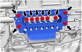
(b) Remove the No. 1 HV battery protector.
Click here
|
(c) Check the connector connections and contact pressure of the relevant terminals for the battery ECU assembly. Click here
OK: The connectors are connected securely and there are no contact problems. Result:
|
|
||||||||||||||||
(d) Install the No. 1 HV battery protector.
| B |
|
CONNECT SECURELY |
| C |
|
| D |
|
|
|
3. |
CHECK FREEZE FRAME DATA (HV BATTERY) |
(a) Connect the Techstream to the DLC3.
(b) Turn the power switch on (IG).
(c) Enter the following menus: Powertrain / HV battery / Trouble Codes.
(d) Read the value of freeze frame data items "Hybrid/EV Battery Cell 1 Voltage" through "Hybrid/EV Battery Cell 56 Voltage" for DTC P0E2D00 and make a note if the value of any is 1.6 V or less.
Powertrain > HV Battery > Trouble Codes
|
Result |
Proceed to |
|---|---|
|
The voltage of any hybrid battery cell from 1 to 19 is 1.6 V or less. |
A |
|
The voltage of any hybrid battery cell from 20 to 28 is 1.6 V or less. |
B |
|
The voltage of any hybrid battery cell from 29 to 37 is 1.6 V or less. |
C |
|
The voltage of any hybrid battery cell from 38 to 56 is 1.6 V or less. |
D |
|
Other than above |
E |
(e) Turn the power switch off.
| B |
|
| C |
|
| D |
|
| E |
|
|
|
4. |
CHECK NO. 1 HV SUPPLY STACK SUB-ASSEMBLY (HYBRID BATTERY CELL 1 TO 19 VOLTAGE) |
CAUTION:
- Be sure to wear insulated gloves and protective goggles.
- Disconnect only the connector corresponding to the HV battery cell to be checked. Do not disconnect the other connectors.
NOTICE:
Make sure to use tester probes with a diameter of approximately 0.5 mm (0.0197 in.) when measuring the voltage of each HV battery cell.
(a) Check that the service plug grip is not installed.
NOTICE:
After removing the service plug grip, do not turn the power switch on (READY), unless instructed by the repair manual because this may cause a malfunction.
(b) Remove the No. 1 HV battery protector.
Click here
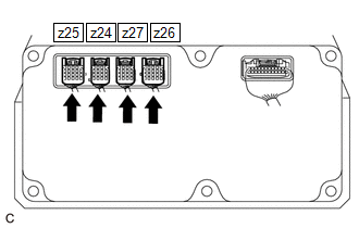
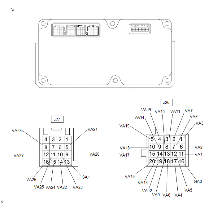
(c) Disconnect the z26 battery ECU assembly connector.
|
(d) Measure the voltage according to the value(s) in the table below. HINT: Measure the voltage of the HV battery cells whose value in the freeze frame data was 1.6 V or less only.
CAUTION: Make sure not to cross the electrodes of an electrical tester measurement terminals. NOTICE: Make sure to check the polarity of each terminal (positive (+) or negative (-)) before connecting a tester. |
|
|
Result |
Proceed to |
|---|---|
|
The voltage between the terminals is 1.6 V or less. |
A |
|
Other than above |
B |
(e) Reconnect the z26 battery ECU assembly connector.
(f) Install the No. 1 HV battery protector.
| A |
|
| B |
|
|
5. |
CHECK NO. 1 HV SUPPLY STACK SUB-ASSEMBLY (HYBRID BATTERY CELL 20 TO 28 VOLTAGE) |
CAUTION:
- Be sure to wear insulated gloves and protective goggles.
- Disconnect only the connector corresponding to the HV battery cell to be checked. Do not disconnect the other connectors.
NOTICE:
Make sure to use tester probes with a diameter of approximately 0.5 mm (0.0197 in.) when measuring the voltage of each HV battery cell.
(a) Check that the service plug grip is not installed.
NOTICE:
After removing the service plug grip, do not turn the power switch on (READY), unless instructed by the repair manual because this may cause a malfunction.
(b) Remove the No. 1 HV battery protector.
Click here
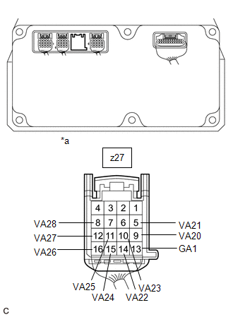
(c) Disconnect the z27 battery ECU assembly connector.
|
(d) Measure the voltage according to the value(s) in the table below. HINT: Measure the voltage of the HV battery cells whose value in the freeze frame data was 1.6 V or less only.
CAUTION: Make sure not to cross the electrodes of an electrical tester measurement terminals. NOTICE: Make sure to check the polarity of each terminal (positive (+) or negative (-)) before connecting a tester. |
|
|
Result |
Proceed to |
|---|---|
|
The voltage between the terminals is 1.6 V or less. |
A |
|
Other than above |
B |
(e) Reconnect the z27 battery ECU assembly connector.
(f) Install the No. 1 HV battery protector.
| B |
|
|
|
6. |
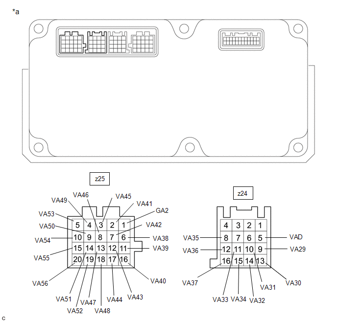
CHECK BATTERY ECU ASSEMBLY (GA0 - VA28) |
NOTICE:
Make sure to use tester probes with a diameter of approximately 0.5 mm (0.0197 in.) when measuring the resistance.
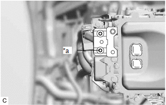
(a) Remove the battery ECU assembly.
Click here
(b) Measure the resistance according to the value(s) in the table below.
HINT:
Only inspect the terminals of the battery ECU assembly which correspond to the HV battery cells which measured 1.6 V or less in the previous step.
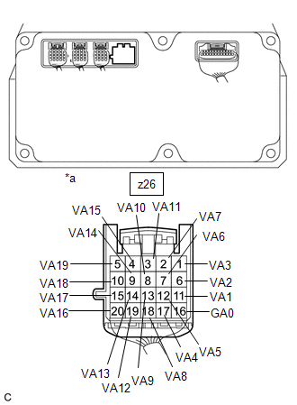
|
*a |
Component without harness connected (Battery ECU Assembly) |
- |
- |
Standard Resistance:
|
Hybrid Battery Cell |
Tester Connection (Tester Probe Polarity) |
Condition |
Specified Condition |
|---|---|---|---|
|
1 |
z26-16 (GA0) (-) - z26-11 (VA1) (+) |
Always |
50 kΩ or more |
|
2 |
z26-11 (VA1) (-) - z26-6 (VA2) (+) |
Always |
50 kΩ or more |
|
3 |
z26-6 (VA2) (-) - z26-1 (VA3) (+) |
Always |
50 kΩ or more |
|
4 |
z26-1 (VA3) (-) - z26-17 (VA4) (+) |
Always |
50 kΩ or more |
|
5 |
z26-17 (VA4) (-) - z26-12 (VA5) (+) |
Always |
50 kΩ or more |
|
6 |
z26-12 (VA5) (-) - z26-7 (VA6) (+) |
Always |
50 kΩ or more |
|
7 |
z26-7 (VA6) (-) - z26-2 (VA7) (+) |
Always |
50 kΩ or more |
|
8 |
z26-2 (VA7) (-) - z26-18 (VA8) (+) |
Always |
50 kΩ or more |
|
9 |
z26-18 (VA8) (-) - z26-13 (VA9) (+) |
Always |
50 kΩ or more |
|
10 |
z26-13 (VA9) (-) - z26-8 (VA10) (+) |
Always |
50 kΩ or more |
|
11 |
z26-8 (VA10) (-) - z26-3 (VA11) (+) |
Always |
50 kΩ or more |
|
12 |
z26-3 (VA11) (-) - z26-19 (VA12) (+) |
Always |
50 kΩ or more |
|
13 |
z26-19 (VA12) (-) - z26-14 (VA13) (+) |
Always |
50 kΩ or more |
|
14 |
z26-14 (VA13) (-) - z26-9 (VA14) (+) |
Always |
50 kΩ or more |
|
15 |
z26-9 (VA14) (-) - z26-4 (VA15) (+) |
Always |
50 kΩ or more |
|
16 |
z26-4 (VA15) (-) - z26-20 (VA16) (+) |
Always |
50 kΩ or more |
|
17 |
z26-20 (VA16) (-) - z26-15 (VA17) (+) |
Always |
50 kΩ or more |
|
18 |
z26-15 (VA17) (-) - z26-10 (VA18) (+) |
Always |
50 kΩ or more |
|
19 |
z26-10 (VA18) (-) - z26-5 (VA19) (+) |
Always |
50 kΩ or more |
|
20 |
z27-13 (GA1) (-) - z27-9 (VA20) (+) |
Always |
50 kΩ or more |
|
21 |
z27-9 (VA20) (-) - z27-5 (VA21) (+) |
Always |
50 kΩ or more |
|
22 |
z27-5 (VA21) (-) - z27-14 (VA22) (+) |
Always |
50 kΩ or more |
|
23 |
z27-14 (VA22) (-) - z27-10 (VA23) (+) |
Always |
50 kΩ or more |
|
24 |
z27-10 (VA23) (-) - z27-15 (VA24) (+) |
Always |
50 kΩ or more |
|
25 |
z27-15 (VA24) (-) - z27-11 (VA25) (+) |
Always |
50 kΩ or more |
|
26 |
z27-11 (VA25) (-) - z27-16 (VA26) (+) |
Always |
50 kΩ or more |
|
27 |
z27-16 (VA26) (-) - z27-12 (VA27) (+) |
Always |
50 kΩ or more |
|
28 |
z27-12 (VA27) (-) - z27-8 (VA28) (+) |
Always |
50 kΩ or more |
NOTICE:
- Make sure to check the polarity of each terminal (positive (+) or negative (-)) before connecting a tester.
- Read the resistance after the value has stabilized.
- In order to avoid damaging the terminals of the battery ECU assembly, make sure to use tester probes with a diameter of approximately 0.5 mm (0.0197 in.) when measuring the resistance of the battery ECU assembly.
(c) Install the battery ECU assembly.
|
Result |
Proceed to |
|---|---|
|
The voltage between the terminals is 50 kΩ or more. |
A |
|
Other than above |
B |
| A |
|
|
|
7. |
REPLACE NO. 1 HV SUPPLY STACK SUB-ASSEMBLY |
Click here
| NEXT |
|
|
8. |
CHECK NO. 2 HV SUPPLY STACK SUB-ASSEMBLY (HYBRID BATTERY CELL 29 TO 37 VOLTAGE) |
CAUTION:
- Be sure to wear insulated gloves and protective goggles.
- Disconnect only the connector corresponding to the HV battery cell to be checked. Do not disconnect the other connectors.
NOTICE:
Make sure to use tester probes with a diameter of approximately 0.5 mm (0.0197 in.) when measuring the voltage of each HV battery cell.
(a) Check that the service plug grip is not installed.
NOTICE:
After removing the service plug grip, do not turn the power switch on (READY), unless instructed by the repair manual because this may cause a malfunction.
(b) Remove the No. 1 HV battery protector.
Click here
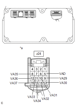
(c) Disconnect the z24 battery ECU assembly connector.
|
(d) Measure the voltage according to the value(s) in the table below. HINT: Measure the voltage of the HV battery cells whose value in the freeze frame data was 1.6 V or less only.
CAUTION: Make sure not to cross the electrodes of an electrical tester measurement terminals. NOTICE: Make sure to check the polarity of each terminal (positive (+) or negative (-)) before connecting a tester. |
|
|
Result |
Proceed to |
|---|---|
|
The voltage between the terminals is 1.6 V or less. |
A |
|
Other than above |
B |
(e) Reconnect the z24 battery ECU assembly connector.
(f) Install the No. 1 HV battery protector.
| A |
|
| B |
|
|
9. |
CHECK NO. 2 HV SUPPLY STACK SUB-ASSEMBLY (HYBRID BATTERY CELL 38 TO 56 VOLTAGE) |
CAUTION:
- Be sure to wear insulated gloves and protective goggles.
- Disconnect only the connector corresponding to the HV battery cell to be checked. Do not disconnect the other connectors.
NOTICE:
Make sure to use tester probes with a diameter of approximately 0.5 mm (0.0197 in.) when measuring the voltage of each HV battery cell.
(a) Check that the service plug grip is not installed.
NOTICE:
After removing the service plug grip, do not turn the power switch on (READY), unless instructed by the repair manual because this may cause a malfunction.
(b) Remove the No. 1 HV battery protector.
Click here
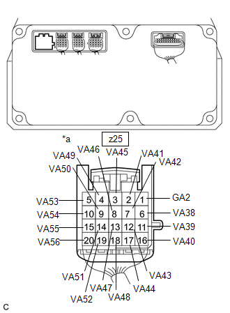
(c) Disconnect the z25 battery ECU assembly connector.
|
(d) Measure the voltage according to the value(s) in the table below. HINT: Measure the voltage of the HV battery cells whose value in the freeze frame data was 1.6 V or less only.
CAUTION: Make sure not to cross the electrodes of an electrical tester measurement terminals. NOTICE: Make sure to check the polarity of each terminal (positive (+) or negative (-)) before connecting a tester. |
|
|
Result |
Proceed to |
|---|---|
|
The voltage between the terminals is 1.6 V or less. |
A |
|
Other than above |
B |
(e) Reconnect the z25 battery ECU assembly connector.
(f) Install the No. 1 HV battery protector.
| B |
|
|
|
10. |
CHECK BATTERY ECU ASSEMBLY (VAD - VA56) |
NOTICE:
Make sure to use tester probes with a diameter of approximately 0.5 mm (0.0197 in.) when measuring the resistance.
(a) Remove the battery ECU assembly.
Click here
(b) Measure the resistance according to the value(s) in the table below.
HINT:
Only inspect the terminals of the battery ECU assembly which correspond to the HV battery cells which measured 1.6 V or less in the previous step.
|
*a |
Component without harness connected (Battery ECU Assembly) |
- |
- |
Standard Resistance:
|
Hybrid Battery Cell |
Tester Connection (Tester Probe Polarity) |
Condition |
Specified Condition |
|---|---|---|---|
|
29 |
z24-5 (VAD) (-) - z24-9 (VA29) (+) |
Always |
50 kΩ or more |
|
30 |
z24-9 (VA29) (-) - z24-13 (VA30) (+) |
Always |
50 kΩ or more |
|
31 |
z24-13 (VA30) (-) - z24-10 (VA31) (+) |
Always |
50 kΩ or more |
|
32 |
z24-10 (VA31) (-) - z24-14 (VA32) (+) |
Always |
50 kΩ or more |
|
33 |
z24-14 (VA32) (-) - z24-11 (VA33) (+) |
Always |
50 kΩ or more |
|
34 |
z24-11 (VA33) (-) - z24-15 (VA34) (+) |
Always |
50 kΩ or more |
|
35 |
z24-15 (VA34) (-) - z24-8 (VA35) (+) |
Always |
50 kΩ or more |
|
36 |
z24-8 (VA35) (-) - z24-12 (VA36) (+) |
Always |
50 kΩ or more |
|
37 |
z24-12 (VA36) (-) - z24-16 (VA37) (+) |
Always |
50 kΩ or more |
|
38 |
z25-1 (GA2) (-) - z25-6 (VA38) (+) |
Always |
50 kΩ or more |
|
39 |
z25-6 (VA38) (-) - z25-11 (VA39) (+) |
Always |
50 kΩ or more |
|
40 |
z25-11 (VA39) (-) - z25-16 (VA40) (+) |
Always |
50 kΩ or more |
|
41 |
z25-16 (VA40) (-) - z25-2 (VA41) (+) |
Always |
50 kΩ or more |
|
42 |
z25-2 (VA41) (-) - z25-7 (VA42) (+) |
Always |
50 kΩ or more |
|
43 |
z25-7 (VA42) (-) - z25-12 (VA43) (+) |
Always |
50 kΩ or more |
|
44 |
z25-12 (VA43) (-) - z25-17 (VA44) (+) |
Always |
50 kΩ or more |
|
45 |
z25-17 (VA44) (-) - z25-3 (VA45) (+) |
Always |
50 kΩ or more |
|
46 |
z25-3 (VA45) (-) - z25-8 (VA46) (+) |
Always |
50 kΩ or more |
|
47 |
z25-8 (VA46) (-) - z25-13 (VA47) (+) |
Always |
50 kΩ or more |
|
48 |
z25-13 (VA47) (-) - z25-18 (VA48) (+) |
Always |
50 kΩ or more |
|
49 |
z25-18 (VA48) (-) - z25-4 (VA49) (+) |
Always |
50 kΩ or more |
|
50 |
z25-4 (VA49) (-) - z25-9 (VA50) (+) |
Always |
50 kΩ or more |
|
51 |
z25-9 (VA50) (-) - z25-14 (VA51) (+) |
Always |
50 kΩ or more |
|
52 |
z25-14 (VA51) (-) - z25-19 (VA52) (+) |
Always |
50 kΩ or more |
|
53 |
z25-19 (VA52) (-) - z25-5 (VA53) (+) |
Always |
50 kΩ or more |
|
54 |
z25-5 (VA53) (-) - z25-10 (VA54) (+) |
Always |
50 kΩ or more |
|
55 |
z25-10 (VA54) (-) - z25-15 (VA55) (+) |
Always |
50 kΩ or more |
|
56 |
z25-15 (VA55) (-) - z25-20 (VA56) (+) |
Always |
50 kΩ or more |
NOTICE:
- Make sure to check the polarity of each terminal (positive (+) or negative (-)) before connecting a tester.
- Read the resistance after the value has stabilized.
- In order to avoid damaging the terminals of the battery ECU assembly, make sure to use tester probes with a diameter of approximately 0.5 mm (0.0197 in.) when measuring the resistance of the battery ECU assembly.
(c) Install the battery ECU assembly.
|
Result |
Proceed to |
|---|---|
|
The voltage between the terminals is 50 kΩ or more. |
A |
|
Other than above |
B |
| A |
|
|
|
11. |
REPLACE NO. 2 HV SUPPLY STACK SUB-ASSEMBLY |
HINT:
Click here
| NEXT |
|
|
12. |
CLEAR DTC (HV BATTERY) |
Click here
|
|
13. |
CHECK DTC OUTPUT (HV BATTERY) |
(a) Connect the Techstream to the DLC3.
(b) Turn the power switch on (IG).
(c) Enter the following menus: Powertrain / HV Battery / Trouble Codes.
(d) Check for DTCs.
Powertrain > HV Battery > Trouble Codes
|
Result |
Proceed to |
|---|---|
|
"P0E2D00" is output. |
A |
|
"P0E2D00" is not output. |
B |
(e) Turn the power switch off.
| B |
|
|
|
14. |
SIMULATION TEST |
NOTICE:
Do not turn the power switch off while performing this inspection.
(a) With the vehicle stopped and the shift position in P, turn the power switch on (IG) and wait for at least 70 seconds.
(b) Turn the power switch on (READY) and without depressing the accelerator pedal, and while depressing the brake pedal, change the shift position to D and wait for 1 minutes. (Step A)
(c) Drive the vehicle 0.5 m (1.6 ft.) forward and perform step A.
(d) Drive the vehicle another 0.5 m (1.6 ft.) forward and perform step A. Repeat this procedure 5 times (minimum total driving distance: 2 m (6.6 ft.)).
(e) Enter the following menus: Powertrain / Hybrid Control / Trouble Codes.
(f) Check if DTCs are output.
Powertrain > Hybrid Control > Trouble Codes
|
Result |
Proceed to |
|---|---|
|
"P0AA649" is not output. |
A |
|
"P0AA649" is output. |
B |
(g) Turn the power switch off.
| B |
|
|
|
15. |
CHECK DTC OUTPUT (HV BATTERY) |
(a) Connect the Techstream to the DLC3.
(b) Turn the power switch on (IG).
(c) Enter the following menus: Powertrain / HV Battery / Trouble Codes.
(d) Check for DTCs.
Powertrain > HV Battery > Trouble Codes
|
Result |
Proceed to |
|---|---|
|
"P0E2D00" is not output. |
A |
|
"P0E2D00" is output. |
B |
(e) Turn the power switch off.
| A |
|
|
|
16. |
CHECK INVERTER WITH CONVERTER ASSEMBLY |
CAUTION:
Be sure to wear insulated gloves.
(a) Check that the service plug grip is not installed.
NOTICE:
After removing the service plug grip, do not turn the power switch on (READY), unless instructed by the repair manual because this may cause a malfunction.
|
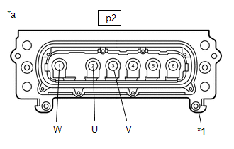
(b) Disconnect the motor cable from the inverter with converter assembly. HINT: Make sure that no foreign matter, coolant or water enters the inverter with converter assembly. |
|
|
(c) Using a megohmmeter set to 500 V, measure the resistance according to the value(s) in the table below. NOTICE: Be sure to set the megohmmeter to 500 V when performing this test. Using a setting higher than 500 V can result in damage to the component being inspected. Standard Resistance:
HINT: Perform this inspection with the motor cable disconnected from the inverter with converter assembly. |
|
(d) Reconnect the motor cable to the inverter with converter assembly.
| NG |
|
|
|
17. |
CHECK HYBRID VEHICLE TRANSAXLE ASSEMBLY (MOTOR CABLE (FOR MG2)) |
CAUTION:
Be sure to wear insulated gloves.
(a) Check that the service plug grip is not installed.
NOTICE:
After removing the service plug grip, do not turn the power switch on (READY), unless instructed by the repair manual because this may cause a malfunction.
|
(b) Disconnect the motor cable from the inverter with converter assembly. HINT: Make sure that no foreign matter, coolant or water enters the inverter with converter assembly. |
|
(c) Connect the cable to the negative (-) auxiliary battery terminal.
HINT:
As the insulation resistance may vary when motor (MG2) rotates, perform this inspection while rotating the front wheels.
(d) Turn the power switch on (IG).
NOTICE:
Turning the power switch on (IG) with the service plug grip removed causes DTCs to be stored. Clear the DTCs after performing this inspection.
(e) Move the shift lever to N and lift the vehicle.
(f) Turn the power switch off.
|
(g) Using a megohmmeter set to 500 V, measure the resistance according to the value(s) in the table below while rotating the front wheels 2 revolutions in the same direction simultaneously. NOTICE:
Standard Resistance:
|
|
(h) Lower the vehicle and move the shift lever to P.
(i) Disconnect the cable from the negative (-) auxiliary battery terminal.
(j) Reconnect the motor cable to the inverter with converter assembly.
| NG |
|
|
|
18. |
CHECK HYBRID VEHICLE TRANSAXLE ASSEMBLY (MOTOR CABLE (FOR MG1)) |
CAUTION:
Be sure to wear insulated gloves.
(a) Check that the service plug grip is not installed.
NOTICE:
After removing the service plug grip, do not turn the power switch on (READY), unless instructed by the repair manual because this may cause a malfunction.
|
(b) Disconnect the motor cable from the inverter with converter assembly. HINT: Make sure that no foreign matter, coolant or water enters the inverter with converter assembly. |
|
(c) Connect the cable to the negative (-) auxiliary battery terminal.
HINT:
As the insulation resistance may vary when generator (MG1) rotates, perform this inspection while rotating the front wheels.
(d) Turn the power switch on (IG).
NOTICE:
Turning the power switch on (IG) with the service plug grip removed causes DTCs to be stored. Clear the DTCs after performing this inspection.
(e) Move the shift lever to N and lift the vehicle.
(f) Turn the power switch off.
|
(g) Using a megohmmeter set to 500 V, measure the resistance according to the value(s) in the table below while rotating the front wheels 2 revolutions in the same direction simultaneously. NOTICE:
Standard Resistance:
|
|
(h) Lower the vehicle and move the shift lever to P.
(i) Disconnect the cable from the negative (-) auxiliary battery terminal.
(j) Reconnect the motor cable to the inverter with converter assembly.
| OK |
|
|
|
19. |
CHECK MOTOR CABLE (FOR MG1) |
CAUTION:
Be sure to wear insulated gloves.
(a) Check that the service plug grip is not installed.
NOTICE:
After removing the service plug grip, do not turn the power switch on (READY), unless instructed by the repair manual because this may cause a malfunction.
(b) Remove the motor cable from the hybrid vehicle transaxle assembly.
Click here
|
(c) Using a megohmmeter set to 500 V, measure the resistance according to the value(s) in the table below. NOTICE: Be sure to set the megohmmeter to 500 V when performing this test. Using a setting higher than 500 V can result in damage to the component being inspected. Standard Resistance:
|
|
(d) Install the motor cable to the hybrid vehicle transaxle assembly.
| OK |
|
| NG |
|
|
20. |
CHECK MOTOR CABLE (FOR MG2) |
CAUTION:
Be sure to wear insulated gloves.
(a) Check that the service plug grip is not installed.
NOTICE:
After removing the service plug grip, do not turn the power switch on (READY), unless instructed by the repair manual because this may cause a malfunction.
(b) Remove the motor cable from the hybrid vehicle transaxle assembly.
Click here
|
(c) Using a megohmmeter set to 500 V, measure the resistance according to the value(s) in the table below. NOTICE: Be sure to set the megohmmeter to 500 V when performing this test. Using a setting higher than 500 V can result in damage to the component being inspected. Standard Resistance:
|
|
(d) Install the motor cable to the hybrid vehicle transaxle assembly.
| OK |
|
| NG |
|
|
|
|