| Last Modified: 05-13-2024 | 6.11:8.1.0 | Doc ID: RM100000001KREK |
| Model Year Start: 2020 | Model: GR Corolla | Prod Date Range: [09/2019 - 04/2020] |
| Title: NAVIGATION / MULTI INFO DISPLAY: NAVIGATION SYSTEM: Mute Signal Circuit between Stereo Component Amplifier and Telematics Transceiver; 2020 MY Corolla Corolla Hatchback Corolla HV GR Corolla [09/2019 - 04/2020] | ||
|
Mute Signal Circuit between Stereo Component Amplifier and Telematics Transceiver |
DESCRIPTION
The DCM (telematics transceiver) sends a mute signal to the stereo component amplifier assembly.
The stereo component amplifier assembly controls the volume according to the mute signal from the DCM (telematics transceiver).
WIRING DIAGRAM
for Hatchback Model
for Sedan Model
CAUTION / NOTICE / HINT
NOTICE:
-
Depending on the parts that are replaced during vehicle inspection or maintenance, performing initialization, registration or calibration may be needed. Refer to Precaution for Navigation System.
Click here
![2020 - 2022 MY Corolla Corolla Hatchback Corolla HV GR Corolla [03/2019 - 09/2022]; NAVIGATION / MULTI INFO DISPLAY: NAVIGATION SYSTEM: PRECAUTION](/t3Portal/stylegraphics/info.gif)
-
Before replacing the DCM (telematics transceiver), refer to Registration.
Click here
PROCEDURE
|
1. |
CHECK MODEL |
(a) Choose the model to be inspected.
|
Result |
Proceed to |
|---|---|
|
for Hatchback Model |
A |
|
for Sedan Model |
B |
| B |

|
|

|
2. |
INSPECT DCM (TELEMATICS TRANSCEIVER) |
|
(a) Measure the voltage according to the value(s) in the table below. Standard Voltage:
|
|
| OK |
|
PROCEED TO NEXT SUSPECTED AREA SHOWN IN PROBLEM SYMPTOMS TABLE |
|
|
3. |
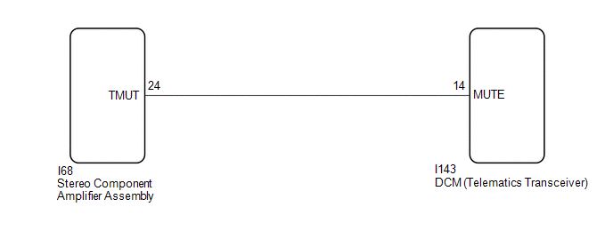
CHECK HARNESS AND CONNECTOR (STEREO COMPONENT AMPLIFIER ASSEMBLY - DCM (TELEMATICS TRANSCEIVER)) |
(a) Disconnect the I68 stereo component amplifier assembly connector.
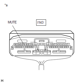
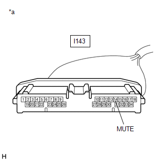
(b) Disconnect the I143 DCM (telematics transceiver) connector.
(c) Measure the resistance according to the value(s) in the table below.
Standard Resistance:
|
Tester Connection |
Condition |
Specified Condition |
|---|---|---|
|
I68-24 (TMUT) - I143-14 (MUTE) |
Always |
Below 1 Ω |
|
I68-24 (TMUT) or I143-14 (MUTE) - Body ground |
Always |
10 kΩ or higher |
| NG |
|
REPAIR OR REPLACE HARNESS OR CONNECTOR |
|
|
4. |
INSPECT STEREO COMPONENT AMPLIFIER ASSEMBLY |
(a) Disconnect the I143 DCM (telematics transceiver) connector.
|
(b) Measure the voltage according to the value(s) in the table below. Standard Voltage:
|
|
| OK |
|
| NG |
|
|
5. |
INSPECT DCM (TELEMATICS TRANSCEIVER) |
|
(a) Measure the voltage according to the value(s) in the table below. Standard Voltage:
|
|
| OK |
|
PROCEED TO NEXT SUSPECTED AREA SHOWN IN PROBLEM SYMPTOMS TABLE |
|
|
6. |
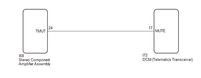
CHECK HARNESS AND CONNECTOR (STEREO COMPONENT AMPLIFIER ASSEMBLY - DCM (TELEMATICS TRANSCEIVER)) |
(a) Disconnect the I68 stereo component amplifier assembly connector.
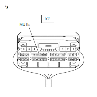
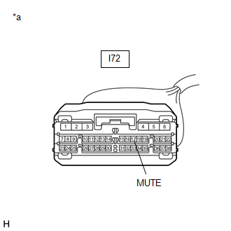
(b) Disconnect the I72 DCM (telematics transceiver) connector.
(c) Measure the resistance according to the value(s) in the table below.
Standard Resistance:
|
Tester Connection |
Condition |
Specified Condition |
|---|---|---|
|
I68-24 (TMUT) - I72-17 (MUTE) |
Always |
Below 1 Ω |
|
I68-24 (TMUT) or I72-17 (MUTE) - Body ground |
Always |
10 kΩ or higher |
| NG |
|
REPAIR OR REPLACE HARNESS OR CONNECTOR |
|
|
7. |
INSPECT STEREO COMPONENT AMPLIFIER ASSEMBLY |
(a) Disconnect the I72 DCM (telematics transceiver) connector.
|
(b) Measure the voltage according to the value(s) in the table below. Standard Voltage:
|
|
| OK |
|
| NG |
|
|
|
|