| Last Modified: 05-13-2024 | 6.11:8.1.0 | Doc ID: RM100000001KREA |
| Model Year Start: 2020 | Model: GR Corolla | Prod Date Range: [09/2019 - 04/2020] |
| Title: NAVIGATION / MULTI INFO DISPLAY: NAVIGATION SYSTEM: Data Signal Circuit between Radio Receiver and Stereo Jack Adapter; 2020 MY Corolla Corolla Hatchback Corolla HV GR Corolla [09/2019 - 04/2020] | ||
|
Data Signal Circuit between Radio Receiver and Stereo Jack Adapter |
DESCRIPTION
The No. 1 stereo jack adapter assembly sends the sound data signal or image data signal from a USB device to the radio and display receiver assembly via this circuit.
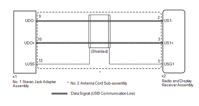
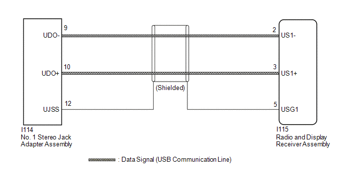
WIRING DIAGRAM
w/o AUX Function
w/ AUX Function
PROCEDURE
|
1. |
CHECK MODEL |
(a) Choose the model to be inspected.
|
Result |
Proceed to |
|---|---|
|
w/o AUX Function |
A |
|
w/ AUX Function |
B |
| B |

|
|

|
2. |
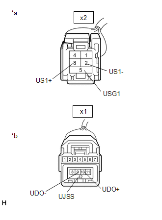
CHECK NO. 2 ANTENNA CORD SUB-ASSEMBLY (RADIO AND DISPLAY RECEIVER ASSEMBLY - NO. 1 STEREO JACK ADAPTER ASSEMBLY) |
(a) Disconnect the x2 radio and display receiver assembly connector.
(b) Disconnect the x1 No. 1 stereo jack adapter assembly connector.
|
(c) Measure the resistance according to the value(s) in the table below. Standard Resistance:
|
|
| OK |
|
PROCEED TO NEXT SUSPECTED AREA SHOWN IN PROBLEM SYMPTOMS TABLE |
| NG |
|
|
3. |
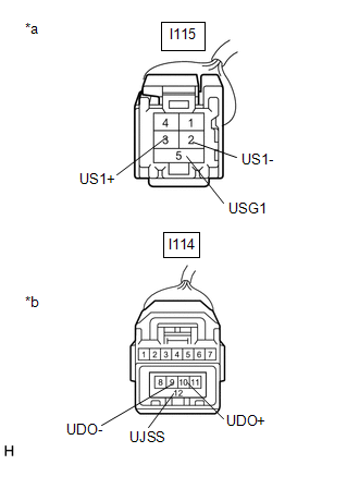
CHECK HARNESS AND CONNECTOR (RADIO AND DISPLAY RECEIVER ASSEMBLY - NO. 1 STEREO JACK ADAPTER ASSEMBLY) |
(a) Disconnect the I115 radio and display receiver assembly connector.
(b) Disconnect the I114 No. 1 stereo jack adapter assembly connector.
|
(c) Measure the resistance according to the value(s) in the table below. Standard Resistance:
|
|
| OK |
|
PROCEED TO NEXT SUSPECTED AREA SHOWN IN PROBLEM SYMPTOMS TABLE |
| NG |
|
REPAIR OR REPLACE HARNESS OR CONNECTOR |
|
|
|