- Short in CAN main bus lines
- Short in CAN branch lines
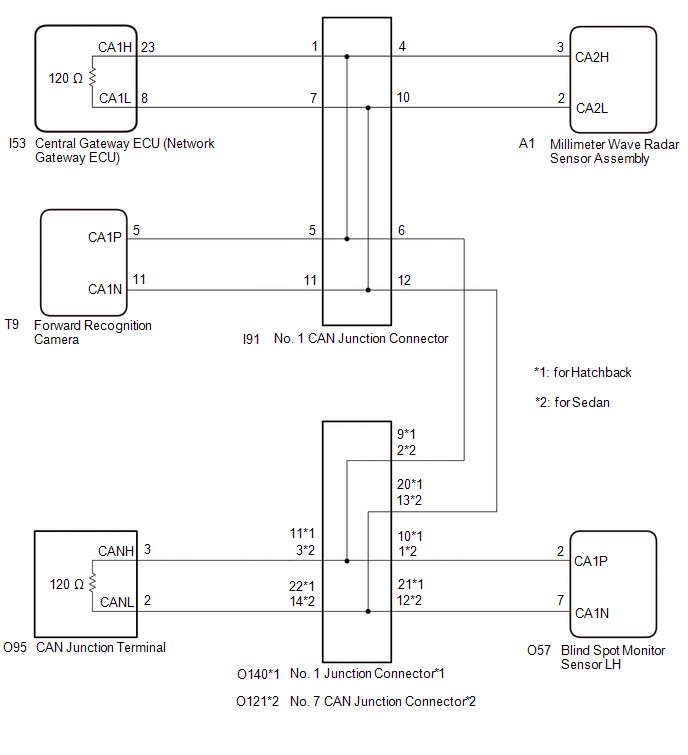
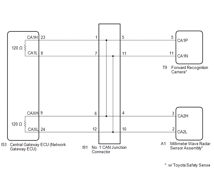
- Central gateway ECU (network gateway ECU)
-
Forward recognition camera
(w/ Toyota Safety Sense)
-
Millimeter wave radar sensor assembly
(w/ Toyota Safety Sense)
-
Blind spot monitor sensor LH
(w/ Blind Spot Monitor System)
- No. 1 CAN junction connector
-
No. 1 junction connector
(for Hatchback with Blind Spot Monitor System)
-
No. 7 CAN junction connector
(for Sedan with Blind Spot Monitor System)
-
CAN junction terminal
(w/ Blind Spot Monitor System)
| Last Modified: 05-13-2024 | 6.11:8.1.0 | Doc ID: RM100000001KH7C |
| Model Year Start: 2020 | Model: GR Corolla | Prod Date Range: [09/2019 - 09/2022] |
| Title: NETWORKING: CAN COMMUNICATION SYSTEM (for Gasoline Model): Check Bus 1 Lines for Short Circuit; 2020 - 2022 MY Corolla Corolla Hatchback GR Corolla [09/2019 - 09/2022] | ||
|
Check Bus 1 Lines for Short Circuit |
DESCRIPTION
There may be a short circuit between the CAN main bus lines and/or CAN branch lines when the resistance between terminals 23 (CA1H) and 8 (CA1L) of the central gateway ECU (network gateway ECU) is below 54 Ω.
|
Symptom |
Trouble Area |
|---|---|
|
Resistance between terminals 23 (CA1H) and 8 (CA1L) of the central gateway ECU (network gateway ECU) is below 54 Ω. |
|
WIRING DIAGRAM
w/ Blind Spot Monitor System
w/o Blind Spot Monitor System
CAUTION / NOTICE / HINT
CAUTION:
When performing the confirmation driving pattern, obey all speed limits and traffic laws.
NOTICE:
-
Because the order of diagnosis is important to allow correct diagnosis, make sure to begin troubleshooting using How to Proceed with Troubleshooting when CAN communication system related DTCs are output.
Click here
![2019 - 2022 MY Corolla Corolla Hatchback GR Corolla [06/2018 - 09/2022]; NETWORKING: CAN COMMUNICATION SYSTEM (for Gasoline Model): HOW TO PROCEED WITH TROUBLESHOOTING](/t3Portal/stylegraphics/info.gif)
- Before measuring the resistance of the CAN bus, turn the ignition switch off and leave the vehicle for 1 minute or more without operating the key or any switches, or opening or closing the doors. After that, disconnect the cable from the negative (-) battery terminal and leave the vehicle for 1 minute or more before measuring the resistance.
-
After turning the ignition switch off, waiting time may be required before disconnecting the cable from the negative (-) battery terminal. Therefore, make sure to read the disconnecting the cable from the negative (-) battery terminal notices before proceeding with work.
Click here
-
After performing repairs, perform the DTC check procedure and confirm that the DTCs are not output again.
DTC check procedure: Turn the ignition switch to ON and wait for 1 minute or more. Then operate the suspected malfunctioning system and drive the vehicle at 60 km/h (37 mph) or more for 5 minutes or more.
-
After the repair, perform the CAN bus check and check that all the ECUs and sensors connected to the CAN communication system are displayed as normal.
Click here
HINT:
- Before disconnecting related connectors for inspection, push in on each connector body to check that the connector is not loose or disconnected.
- When a connector is disconnected, check that the terminals and connector body are not cracked, deformed or corroded.
PROCEDURE
|
1. |
CHECK VEHICLE TYPE |
(a) Check vehicle type.
|
Result |
Proceed to |
|---|---|
|
w/ Blind Spot Monitor System |
A |
|
w/o Blind Spot Monitor System |
B |
| B |

|
|

|
2. |
CHECK FOR SHORT IN CAN BUS LINES (NO. 1 CAN JUNCTION CONNECTOR) |
(a) Disconnect the cable from the negative (-) battery terminal.
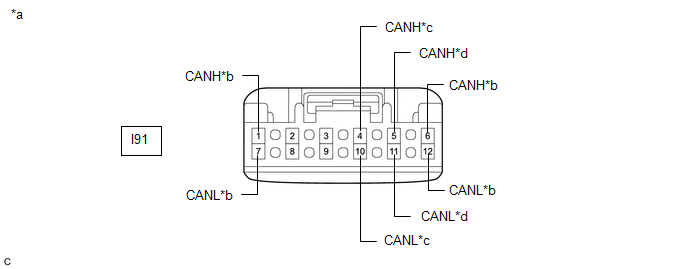
(b) Disconnect the I91 No. 1 CAN junction connector.
(c) Measure the resistance according to the value(s) in the table below.
|
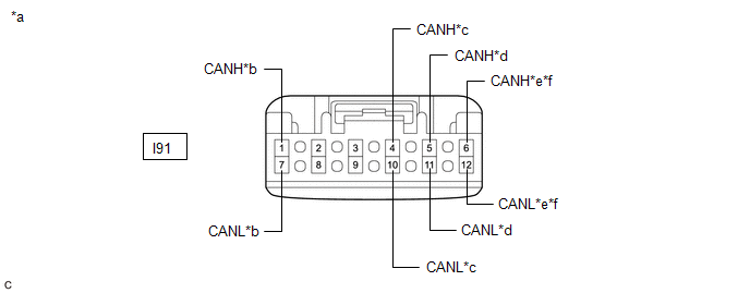
*a |
Front view of wire harness connector (to No. 1 CAN Junction Connector) |
*b |
to Central Gateway ECU (Network Gateway ECU) |
|
*c |
to Millimeter Wave Radar Sensor Assembly |
*d |
to Forward Recognition Camera |
|
*e |
to No. 1 Junction Connector (for Hatchback) |
*f |
to No. 7 CAN Junction Connector (for Sedan) |
Standard Resistance:
|
Tester Connection |
Condition |
Specified Condition |
Connected to |
|---|---|---|---|
|
I91-1 (CANH) - I91-7 (CANL) |
Cable disconnected from negative (-) battery terminal |
108 to 132 Ω |
Central gateway ECU (network gateway ECU) |
|
I91-4 (CANH) - I91-10 (CANL) |
Cable disconnected from negative (-) battery terminal |
200 Ω or higher |
Millimeter wave radar sensor assembly |
|
I91-5 (CANH) - I91-11 (CANL) |
Cable disconnected from negative (-) battery terminal |
200 Ω or higher |
Forward recognition camera |
|
I91-6 (CANH) - I91-12 (CANL) |
Cable disconnected from negative (-) battery terminal |
108 to 132 Ω |
No. 1 junction connector*1 |
|
I91-6 (CANH) - I91-12 (CANL) |
Cable disconnected from negative (-) battery terminal |
108 to 132 Ω |
No. 7 CAN junction connector*2 |
- *1: for Hatchback
- *2: for Sedan
|
Result |
Proceed to |
|---|---|
|
OK |
A |
|
NG (Line to central gateway ECU (network gateway ECU)) |
B |
|
NG (Line to No. 1 junction connector (for Hatchback)) |
C |
|
NG (Line to No. 7 CAN junction connector (for Sedan)) |
D |
|
NG (Line to ECU or sensor) |
E |
| A |
|
REPLACE NO. 1 CAN JUNCTION CONNECTOR |
| C |
|
| D |
|
| E |
|
|
|
3. |
CHECK FOR SHORT IN CAN BUS LINES (NO. 1 CAN JUNCTION CONNECTOR - CENTRAL GATEWAY ECU (NETWORK GATEWAY ECU)) |
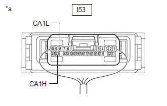
(a) Disconnect the I53 central gateway ECU (network gateway ECU) connector.
(b) Measure the resistance according to the value(s) in the table below.
|
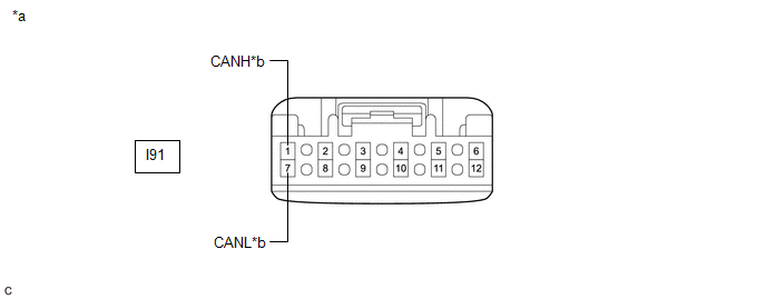
*a |
Front view of wire harness connector (to No. 1 CAN Junction Connector) |
*b |
to Central Gateway ECU (Network Gateway ECU) |
Standard Resistance:
|
Tester Connection |
Condition |
Specified Condition |
|---|---|---|
|
I91-1 (CANH) - I91-7 (CANL) |
Cable disconnected from negative (-) battery terminal |
1 MΩ or higher |
| OK |
|
| NG |
|
REPAIR OR REPLACE CAN MAIN BUS LINES OR CONNECTOR (NO. 1 CAN JUNCTION CONNECTOR - CENTRAL GATEWAY ECU (NETWORK GATEWAY ECU)) |
|
4. |
CHECK FOR SHORT IN CAN BUS LINES (NO. 1 JUNCTION CONNECTOR) |
(a) Reconnect the I91 No. 1 CAN junction connector.
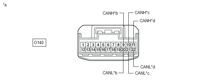
(b) Disconnect the O140 No. 1 junction connector.
(c) Measure the resistance according to the value(s) in the table below.
|
*a |
Front view of wire harness connector (to No. 1 Junction Connector) |
*b |
to No. 1 CAN Junction Connector |
|
*c |
to Blind Spot Monitor Sensor LH |
*d |
to CAN Junction Terminal |
Standard Resistance:
|
Tester Connection |
Condition |
Specified Condition |
Connected to |
|---|---|---|---|
|
O140-9 (CANH) - O140-20 (CANL) |
Cable disconnected from negative (-) battery terminal |
108 to 132 Ω |
No. 1 CAN junction connector |
|
O140-10 (CANH) - O140-21 (CANL) |
Cable disconnected from negative (-) battery terminal |
200 Ω or higher |
Blind spot monitor sensor LH |
|
O140-11 (CANH) - O140-22 (CANL) |
Cable disconnected from negative (-) battery terminal |
108 to 132 Ω |
CAN junction terminal |
|
Result |
Proceed to |
|---|---|
|
OK |
A |
|
NG (Line to No. 1 CAN junction connector) |
B |
|
NG (Line to CAN junction terminal) |
C |
|
NG (Line to ECU or sensor) |
D |
| A |
|
REPLACE NO. 1 JUNCTION CONNECTOR |
| B |
|
REPAIR OR REPLACE CAN MAIN BUS LINES OR CONNECTOR (NO. 1 JUNCTION CONNECTOR - NO. 1 CAN JUNCTION CONNECTOR) |
| D |
|
|
|
5. |
CHECK FOR SHORT IN CAN BUS LINES (NO. 1 JUNCTION CONNECTOR - CAN JUNCTION TERMINAL) |
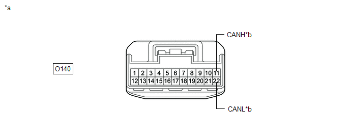
(a) Disconnect the O95 CAN junction terminal connector.
(b) Measure the resistance according to the value(s) in the table below.
|
*a |
Front view of wire harness connector (to No. 1 Junction Connector) |
*b |
to CAN Junction Terminal |
Standard Resistance:
|
Tester Connection |
Condition |
Specified Condition |
|---|---|---|
|
O140-11 (CANH) - O140-22 (CANL) |
Cable disconnected from negative (-) battery terminal |
1 MΩ or higher |
| OK |
|
REPLACE CAN JUNCTION TERMINAL |
| NG |
|
REPAIR OR REPLACE CAN MAIN BUS LINES OR CONNECTOR (NO. 1 JUNCTION CONNECTOR - CAN JUNCTION TERMINAL) |
|
6. |
CHECK FOR SHORT IN CAN BUS LINES (NO. 7 CAN JUNCTION CONNECTOR) |
(a) Reconnect the I91 No. 1 CAN junction connector.
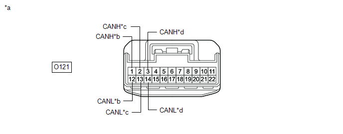
(b) Disconnect the O121 No. 7 CAN junction connector.
(c) Measure the resistance according to the value(s) in the table below.
|
*a |
Front view of wire harness connector (to No. 7 CAN Junction Connector) |
*b |
to Blind Spot Monitor Sensor LH |
|
*c |
to No. 1 CAN Junction Connector |
*d |
to CAN Junction Terminal |
Standard Resistance:
|
Tester Connection |
Condition |
Specified Condition |
Connected to |
|---|---|---|---|
|
O121-1 (CANH) - O121-12 (CANL) |
Cable disconnected from negative (-) battery terminal |
200 Ω or higher |
Blind spot monitor sensor LH |
|
O121-2 (CANH) - O121-13 (CANL) |
Cable disconnected from negative (-) battery terminal |
108 to 132 Ω |
No. 1 CAN junction connector |
|
O121-3 (CANH) - O121-14 (CANL) |
Cable disconnected from negative (-) battery terminal |
108 to 132 Ω |
CAN junction terminal |
|
Result |
Proceed to |
|---|---|
|
OK |
A |
|
NG (Line to No. 1 CAN junction connector) |
B |
|
NG (Line to CAN junction terminal) |
C |
|
NG (Line to ECU or sensor) |
D |
| A |
|
REPLACE NO. 7 CAN JUNCTION CONNECTOR |
| B |
|
REPAIR OR REPLACE CAN MAIN BUS LINES OR CONNECTOR (NO. 7 CAN JUNCTION CONNECTOR - NO. 1 CAN JUNCTION CONNECTOR) |
| D |
|
|
|
7. |
CHECK FOR SHORT IN CAN BUS LINES (NO. 7 CAN JUNCTION CONNECTOR - CAN JUNCTION TERMINAL) |
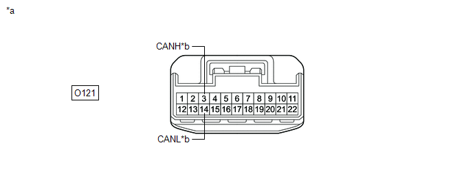
(a) Disconnect the O95 CAN junction terminal connector.
(b) Measure the resistance according to the value(s) in the table below.
|
*a |
Front view of wire harness connector (to No. 7 CAN Junction Connector) |
*b |
to CAN Junction Terminal |
Standard Resistance:
|
Tester Connection |
Condition |
Specified Condition |
|---|---|---|
|
O121-3 (CANH) - O121-14 (CANL) |
Cable disconnected from negative (-) battery terminal |
1 MΩ or higher |
| OK |
|
REPLACE CAN JUNCTION TERMINAL |
| NG |
|
REPAIR OR REPLACE CAN MAIN BUS LINES OR CONNECTOR (NO. 7 CAN JUNCTION CONNECTOR - CAN JUNCTION TERMINAL) |
|
8. |
CHECK FOR SHORT IN CAN BUS LINES (ECU OR SENSOR) |
(a) Reconnect all wire harness connectors.
(b) Disconnect the connector that includes terminals CANH and CANL from the ECU or sensor to which the short circuited branch line is connected.
Click here
|
(c) Measure the resistance according to the value(s) in the table below. Standard Resistance:
HINT:
|
|
| OK |
|
REPLACE ECU OR SENSOR |
| NG |
|
REPAIR OR REPLACE HARNESS OR CONNECTOR |
|
9. |
CHECK FOR SHORT IN CAN BUS LINES (NO. 1 CAN JUNCTION CONNECTOR) |
(a) Disconnect the cable from the negative (-) battery terminal.
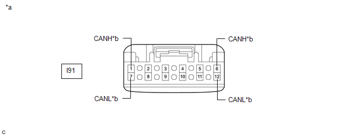
(b) Disconnect the I91 No. 1 CAN junction connector.
(c) Measure the resistance according to the value(s) in the table below.
|
*a |
Front view of wire harness connector (to No. 1 CAN Junction Connector) |
*b |
to Central Gateway ECU (Network Gateway ECU) |
|
*c |
to Millimeter Wave Radar Sensor Assembly (w/ Toyota Safety Sense) |
*d |
to Forward Recognition Camera (w/ Toyota Safety Sense) |
Standard Resistance:
|
Tester Connection |
Condition |
Specified Condition |
Connected to |
|---|---|---|---|
|
I91-1 (CANH) - I91-7 (CANL) |
Cable disconnected from negative (-) battery terminal |
108 to 132 Ω |
Central gateway ECU (network gateway ECU) |
|
I91-4 (CANH) - I91-10 (CANL) |
Cable disconnected from negative (-) battery terminal |
200 Ω or higher |
Millimeter wave radar sensor assembly* |
|
I91-5 (CANH) - I91-11 (CANL) |
Cable disconnected from negative (-) battery terminal |
200 Ω or higher |
Forward recognition camera* |
|
I91-6 (CANH) - I91-12 (CANL) |
Cable disconnected from negative (-) battery terminal |
108 to 132 Ω |
Central gateway ECU (network gateway ECU) |
- *: w/ Toyota Safety Sense
|
Result |
Proceed to |
|---|---|
|
OK |
A |
|
NG (Line to central gateway ECU (network gateway ECU)) |
B |
|
NG (Line to ECU or sensor) |
C |
| A |
|
REPLACE NO. 1 CAN JUNCTION CONNECTOR |
| C |
|
|
|
10. |
CHECK FOR SHORT IN CAN BUS LINES (NO. 1 CAN JUNCTION CONNECTOR - CENTRAL GATEWAY ECU (NETWORK GATEWAY ECU)) |
(a) Disconnect the I53 central gateway ECU (network gateway ECU) connector.
(b) Measure the resistance according to the value(s) in the table below.
|
*a |
Front view of wire harness connector (to No. 1 CAN Junction Connector) |
*b |
to Central Gateway ECU (Network Gateway ECU) |
Standard Resistance:
|
Tester Connection |
Condition |
Specified Condition |
|---|---|---|
|
I91-1 (CANH) - I91-7 (CANL) |
Cable disconnected from negative (-) battery terminal |
1 MΩ or higher |
|
I91-6 (CANH) - I91-12 (CANL) |
Cable disconnected from negative (-) battery terminal |
1 MΩ or higher |
| OK |
|
| NG |
|
REPAIR OR REPLACE CAN MAIN BUS LINES OR CONNECTOR (NO. 1 CAN JUNCTION CONNECTOR - CENTRAL GATEWAY ECU (NETWORK GATEWAY ECU)) |
|
11. |
CHECK FOR SHORT IN CAN BUS LINES (ECU OR SENSOR) |
(a) Reconnect all wire harness connectors.
(b) Disconnect the connector that includes terminals CANH and CANL from the ECU or sensor to which the short circuited branch line is connected.
Click here
|
(c) Measure the resistance according to the value(s) in the table below. Standard Resistance:
HINT:
|
|
| OK |
|
REPLACE ECU OR SENSOR |
| NG |
|
REPAIR OR REPLACE HARNESS OR CONNECTOR |
|
|
|