- DTC judgment completed
- System normal
| Last Modified: 05-13-2024 | 6.11:8.1.0 | Doc ID: RM100000001HTL3 |
| Model Year Start: 2020 | Model: Corolla Hatchback | Prod Date Range: [03/2019 - 09/2022] |
| Title: M20A-FKS (ENGINE CONTROL): SFI SYSTEM: P050031; Vehicle Speed Sensor "A" No Signal; 2020 - 2022 MY Corolla Corolla Hatchback [03/2019 - 09/2022] | ||
|
DTC |
P050031 |
Vehicle Speed Sensor "A" No Signal |
DESCRIPTION
-
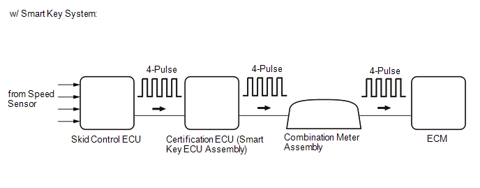
w/ Smart Key System
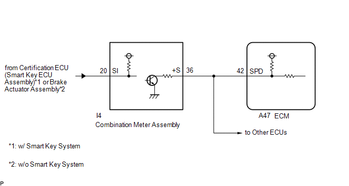
- Vehicles, which are equipped with ABS (Anti-lock Brake System), detect the vehicle speed using the skid control ECU (brake actuator assembly) and speed sensor. The speed sensor monitors the wheel rotation speed and sends a signal to the skid control ECU. The skid control ECU detects the wheel speed of all 4 wheels and outputs a 4-pulse signal to the ECM via the certification ECU (smart key ECU assembly) and combination meter assembly. The ECM determines the vehicle speed based on the frequency of the pulse signal.
-
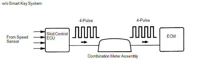
w/o Smart Key System
- Vehicles, which are equipped with ABS (Anti-lock Brake System), detect the vehicle speed using the skid control ECU (brake actuator assembly) and speed sensor. The speed sensor monitors the wheel rotation speed and sends a signal to the skid control ECU. The skid control ECU converts the wheel speed signal into a 4-pulse signal and transmits it to the ECM via the combination meter assembly. The ECM determines the vehicle speed based on the frequency of the pulse signal.
HINT:
- Various systems use the vehicle speed signal distributed from the combination meter assembly. Check all the components possibly related to speed signal.
-
A voltage of 12 V or 5 V is output from each ECU and then input to the combination meter assembly.
The signal is changed to a pulse signal at the transistor in the combination meter assembly. Each ECU controls the respective system based on the pulse signal.
- If a short occurs in any of the ECUs or in the wire harness connected to an ECU, all systems using the speed signal will not operate normally.
|
DTC No. |
Detection Item |
DTC Detection Condition |
Trouble Area |
MIL |
Memory |
Note |
|---|---|---|---|---|---|---|
|
P050031 |
Vehicle Speed Sensor "A" No Signal |
Diagnosis condition:
Abnormal condition:
Malfunction time:
Trip logic:
Detection conditions:
Sensors/components used for detection (Main):
Sensors/components used for detection (Related):
|
|
Comes on |
DTC stored |
|
MONITOR DESCRIPTION
When the vehicle is being driven (for continuously variable transaxle models) or when the vehicle is being driven and fuel cut is being performed (for manual transaxle models), if no vehicle speed signal is received for 5 seconds or more (for continuously variable transaxle models) or for 5.7 seconds or more (for manual transaxle models), the ECM determines that the vehicle speed signal circuit is malfunctioning and illuminates the MIL and stores a DTC.
MONITOR STRATEGY
|
Related DTCs |
P0500: Vehicle speed sensor verify pulse input |
|
Required Sensors/Components (Main) |
Vehicle speed sensor Combination meter assembly Certification ECU (smart key ECU assembly) (w/ Smart Key System) Skid control ECU |
|
Required Sensors/Components (Related) |
Park/neutral position switch assembly (for continuously variable transaxle models) Clutch start switch assembly (for manual transaxle models) Engine coolant temperature sensor Crankshaft position sensor Speed sensor Throttle position sensor Mass air flow meter sub-assembly |
|
Frequency of Operation |
Continuous |
|
Duration |
5 seconds (for continuously variable transaxle models) 5.7 seconds (for manual transaxle models) |
|
MIL Operation |
2 driving cycles |
|
Sequence of Operation |
None |
TYPICAL ENABLING CONDITIONS
for Continuously Variable Transaxle Models:
|
Monitor runs whenever the following DTCs are not present |
None |
|
All of the following conditions are met |
- |
|
Battery voltage |
8 V or higher |
|
Ignition switch |
ON |
|
Starter |
Off |
|
Engine |
Running |
|
Time after ignition switch off to ON |
3 seconds or more |
|
Vehicle speed sensor monitor condition |
Met |
for Manual Transaxle Models:
|
Monitor runs whenever the following DTCs are not present |
None |
|
All of the following conditions are met |
- |
|
Battery voltage |
8 V or higher |
|
Ignition switch |
ON |
|
Starter |
Off |
|
Time after ignition switch off to ON |
3 seconds or more |
|
Fuel-cut |
On |
TYPICAL MALFUNCTION THRESHOLDS
|
Vehicle speed sensor signal |
No signal |
CONFIRMATION DRIVING PATTERN
HINT:
-
After repair has been completed, clear the DTC and then check that the vehicle has returned to normal by performing the following All Readiness check procedure.
Click here
![2019 - 2022 MY Corolla Corolla Hatchback [06/2018 - 09/2022]; M20A-FKS (ENGINE CONTROL): SFI SYSTEM: DTC CHECK / CLEAR](/t3Portal/stylegraphics/info.gif)
-
When clearing the permanent DTCs, refer to the "CLEAR PERMANENT DTC" procedure.
Click here
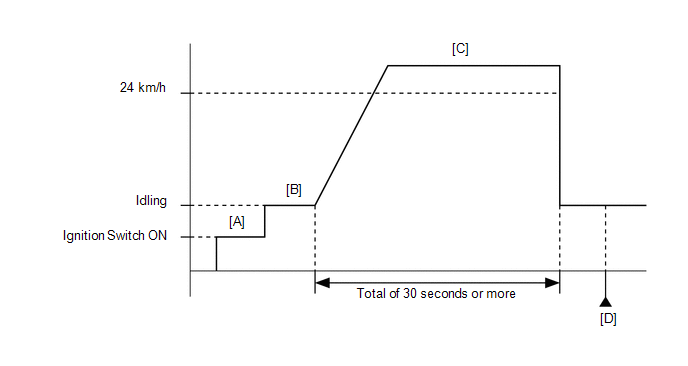
for Continuously Variable Transaxle Models:
- Connect the Techstream to the DLC3.
- Turn the ignition switch to ON.
- Turn the Techstream on.
- Clear the DTCs (even if no DTCs are stored, perform the clear DTC procedure).
- Turn the ignition switch off and wait for at least 30 seconds.
- Turn the ignition switch to ON [A].
- Turn the Techstream on.
- Start the engine [B].
-
Drive the vehicle at 24 km/h (15 mph) or more for a total of 30 seconds or more [C].
CAUTION:
When performing the confirmation driving pattern, obey all speed limits and traffic laws.
- Stop the vehicle.
- Enter the following menus: Powertrain / Engine / Trouble Codes [D].
-
Read the pending DTCs.
HINT:
- If a pending DTC is output, the system is malfunctioning.
- If a pending DTC is not output, perform the following procedure.
- Enter the following menus: Powertrain / Engine / Utility / All Readiness.
- Proceed to the next screen and enter the DTC to be checked.
-
Check the DTC judgment result.
Techstream Display
Description
NORMAL
ABNORMAL
- DTC judgment completed
- System abnormal
INCOMPLETE
- DTC judgment not completed
- Perform driving pattern after confirming DTC enabling conditions
HINT:
- If the judgment result is NORMAL, the system is normal.
- If the judgment result is ABNORMAL, the system has a malfunction.
- If the judgment result is INCOMPLETE, perform steps [C] through [D] again.
-
[A] to [D]: Normal judgment procedure.
The normal judgment procedure is used to complete DTC judgment and also used when clearing permanent DTCs.
- When clearing the permanent DTCs, do not disconnect the cable from the battery terminal or attempt to clear the DTCs during this procedure, as doing so will clear the universal trip and normal judgment histories.
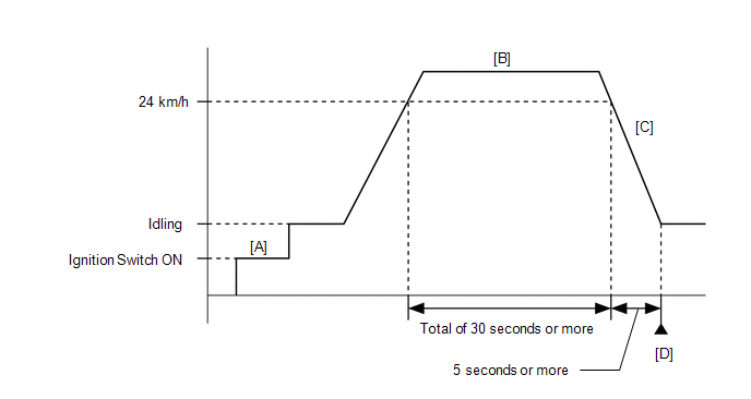
for Manual Transaxle Models:
- Connect the Techstream to the DLC3.
- Turn the ignition switch to ON.
- Turn the Techstream on.
- Clear the DTCs (even if no DTCs are stored, perform the clear DTC procedure).
- Turn the ignition switch off and wait for at least 30 seconds.
- Turn the ignition switch to ON [A].
- Turn the Techstream on.
- Start the engine.
-
Drive the vehicle at 24 km/h (15 mph) or more for a total of 30 seconds or more [B].
CAUTION:
When performing the confirmation driving pattern, obey all speed limits and traffic laws.
- Decelerate the vehicle by releasing the accelerator pedal for 5 seconds or more to perform the fuel-cut [C].
- Stop the vehicle.
- Enter the following menus: Powertrain / Engine / Trouble Codes [D].
-
Read the pending DTCs.
HINT:
- If a pending DTC is output, the system is malfunctioning.
- If a pending DTC is not output, perform the following procedure.
- Enter the following menus: Powertrain / Engine / Utility / All Readiness.
- Proceed to the next screen and enter the DTC to be checked.
-
Check the DTC judgment result.
Techstream Display
Description
NORMAL
- DTC judgment completed
- System normal
ABNORMAL
- DTC judgment completed
- System abnormal
INCOMPLETE
- DTC judgment not completed
- Perform driving pattern after confirming DTC enabling conditions
HINT:
- If the judgment result is NORMAL, the system is normal.
- If the judgment result is ABNORMAL, the system has a malfunction.
- If the judgment result is INCOMPLETE, perform steps [B] through [D] again.
-
[A] to [D]: Normal judgment procedure.
The normal judgment procedure is used to complete DTC judgment and also used when clearing permanent DTCs.
- When clearing the permanent DTCs, do not disconnect the cable from the battery terminal or attempt to clear the DTCs during this procedure, as doing so will clear the universal trip and normal judgment histories.
WIRING DIAGRAM
CAUTION / NOTICE / HINT
HINT:
- Read Freeze Frame Data using the Techstream. The ECM records vehicle and driving condition information as Freeze Frame Data the moment a DTC is stored. When troubleshooting, Freeze Frame Data can help determine if the vehicle was moving or stationary, if the engine was warmed up or not, if the air fuel ratio was lean or rich, and other data from the time the malfunction occurred.
-
If DTC P050031 is output, perform troubleshooting for the transaxle first as the transaxle may have a mechanical malfunction. (for continuously variable transaxle models)
Click here
PROCEDURE
|
1. |
READ VALUE USING TECHSTREAM (VEHICLE SPEED) |
HINT:
This procedure confirms whether the speedometer is operating correctly.
(a) Connect the Techstream to the DLC3.
(b) Turn the ignition switch to ON.
(c) Turn the Techstream on.
(d) Enter the following menus: Powertrain / Engine / Data List / Vehicle Speed.
Powertrain > Engine > Data List
|
Tester Display |
|---|
|
Vehicle Speed |
(e) Drive the vehicle.
(f) Read the value displayed on the Techstream.
|
Result |
Proceed to |
|---|---|
|
Values displayed on Techstream and speedometer display not equal |
A |
|
Values displayed on Techstream and speedometer display equal |
B |
| B |

|
|

|
2. |
CHECK COMBINATION METER SYSTEM |
(a) Check the circuits that send vehicle speed signals to this system in the combination meter system.
Click here
|
|
3. |
CHECK HARNESS AND CONNECTOR (COMBINATION METER ASSEMBLY - ECM) |
(a) Disconnect the combination meter assembly connector.
(b) Disconnect the ECM connector.
(c) Measure the resistance according to the value(s) in the table below.
Standard Resistance:
|
Tester Connection |
Condition |
Specified Condition |
|---|---|---|
|
I4-36 (+S) - A47-42 (SPD) |
Always |
Below 1 Ω |
| OK |
|
| NG |
|
REPAIR OR REPLACE HARNESS OR CONNECTOR |
|
|
|