- DTC judgment completed
- System normal
| Last Modified: 05-13-2024 | 6.11:8.1.0 | Doc ID: RM100000001HT6V |
| Model Year Start: 2020 | Model: Corolla | Prod Date Range: [03/2019 - 11/2022] |
| Title: 2ZR-FAE (ENGINE CONTROL): SFI SYSTEM: U011B; Lost Communication with Rocker Arm Control Module "A"; 2020 - 2023 MY Corolla [03/2019 - 11/2022] | ||
|
DTC |
U011B |
Lost Communication with Rocker Arm Control Module "A" |
DESCRIPTION
The ECM and continuously variable valve lift controller assembly communicate via the CAN communication system.
|
DTC No. |
Detection Item |
DTC Detection Condition |
Trouble Area |
MIL |
Memory |
Note |
|---|---|---|---|---|---|---|
|
U011B |
Lost Communication with Rocker Arm Control Module "A" |
CAN communication stops (1 trip detection logic). |
|
Comes on |
DTC stored |
DTC for Mexico Models - Applies |
MONITOR DESCRIPTION
When between the ECM and the continuously variable valve lift controller assembly is a malfunction in the CAN communication, this DTC is stored and the MIL is illuminated.
MONITOR STRATEGY
|
Related DTCs |
U011B: Lost communication with rocker arm control module verify communication |
|
Required Sensors/Components (Main) |
Continuously variable valve lift controller assembly ECM |
|
Required Sensors/Components (Related) |
- |
|
Frequency of Operation |
Continuous |
|
Duration |
0.19 seconds |
|
MIL Operation |
Immediate |
|
Sequence of Operation |
None |
TYPICAL ENABLING CONDITIONS
|
All of the following conditions are met |
- |
|
Battery voltage |
10.5 V or higher |
|
Ignition switch |
ON |
|
Command to rocker arm control module power |
On |
|
Rocker arm control module power supply line low voltage fail (P104A) |
Not detected |
|
Starter |
Off |
TYPICAL MALFUNCTION THRESHOLDS
|
Communication signal |
Lost communication with rocker arm control module |
CONFIRMATION DRIVING PATTERN
- Connect the Techstream to the DLC3.
- Start the engine and warm it up.
- Turn the Techstream on.
- Clear the DTCs (even if no DTCs are stored, perform the clear DTC procedure).
- Turn the ignition switch off and wait for at least 30 seconds.
- Start the engine and idle it for 20 seconds.
- Turn the Techstream on.
- Clear the DTCs.
- Turn the ignition switch off and wait for at least 30 seconds.
- Start the engine and idle it for 20 seconds.
- Turn the ignition switch off and wait for at least 30 seconds.
- Turn the ignition switch to ON.
- Turn the Techstream on.
- Enter the following menus: Powertrain / Engine and ECT / Trouble Codes.
-
Read the pending DTCs.
HINT:
- If a pending DTC is output, the system is malfunctioning.
- If a pending DTC is not output, perform the following procedure.
- Enter the following menus: Powertrain / Engine and ECT / Utility / All Readiness.
- Input the DTC: U011B.
-
Check the DTC judgment result.
Techstream Display
Description
NORMAL
ABNORMAL
- DTC judgment completed
- System abnormal
INCOMPLETE
- DTC judgment not completed
- Perform driving pattern after confirming DTC enabling conditions
N/A
- Unable to perform DTC judgment
- Number of DTCs which do not fulfill DTC preconditions has reached ECU memory limit
HINT:
- If the judgment result shows NORMAL, the system is normal.
- If the judgment result shows ABNORMAL, the system has a malfunction.
-
If the judgment result is INCOMPLETE or N/A and no pending DTC is output, perform a universal trip and check for permanent DTCs.
Click here
![2020 - 2022 MY Corolla [03/2019 - 09/2022]; 2ZR-FAE (ENGINE CONTROL): SFI SYSTEM: DTC CHECK / CLEAR](/t3Portal/stylegraphics/info.gif)
HINT:
- If a permanent DTC is output, the system is malfunctioning.
- If no permanent DTC is output, the system is normal.
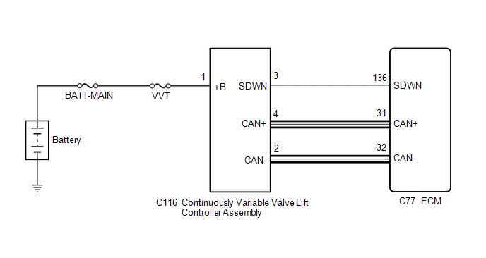
WIRING DIAGRAM
CAUTION / NOTICE / HINT
NOTICE:
-
When one of the following DTCs is output and the MIL is illuminated, actuator position learning is performed during the next trip. After the system returns to normal, actuator position learning is performed during the next trip and the MIL remains illuminated until learning is complete.
Actuator position learning is performed when these DTCs are output.
P1049, P104A, P1055, P2646, P2647, P2648, P2649, P264A, U011B
- Inspect the fuses for circuits related to this system before performing the following procedure.
HINT:
- When there is no power (+B) supplied to the continuously variable valve lift controller assembly, DTC U011B is stored. Also, if the SDWN circuit is open, power supply is stopped and DTC U011B is stored.
- After performing repairs, perform the following procedure and check that DTCs are not output again.
- After using the Techstream to perform minimum valve lift learning, keep the engine idling for 30 seconds to complete learning. Otherwise, the VALVEMATIC system may not operate normally, causing poor acceleration, etc.
- Read Freeze Frame Data using the Techstream. The ECM records vehicle and driving condition information as Freeze Frame Data the moment a DTC is stored. When troubleshooting, Freeze Frame Data can help determine if the vehicle was moving or stationary, if the engine was warmed up or not, if the air fuel ratio was lean or rich, and other data from the time the malfunction occurred.
PROCEDURE
|
1. |
CHECK TERMINAL VOLTAGE (POWER SOURCE OF CONTINUOUSLY VARIABLE VALVE LIFT CONTROLLER ASSEMBLY) |
|
(a) Disconnect the continuously variable valve lift controller assembly connector. |
|
(b) Turn the ignition switch to ON.
(c) Measure the voltage according to the value(s) in the table below.
Standard Voltage:
|
Tester Connection |
Condition |
Specified Condition |
|---|---|---|
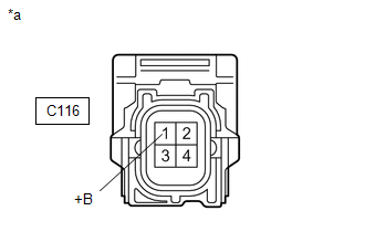
|
C116-1 (+B) - Body ground |
Ignition switch ON |
11 to 14 V |
| NG |

|
REPAIR OR REPLACE HARNESS OR CONNECTOR (CONTINUOUSLY VARIABLE VALVE LIFT CONTROLLER ASSEMBLY - BATTERY) |
|

|
2. |
CHECK HARNESS AND CONNECTOR (CONTINUOUSLY VARIABLE VALVE LIFT CONTROLLER ASSEMBLY - ECM) |
(a) Disconnect the continuously variable valve lift controller assembly connector.
(b) Disconnect the ECM connector.
(c) Measure the resistance according to the value(s) in the table below.
Standard Resistance:
|
Tester Connection |
Condition |
Specified Condition |
|---|---|---|
|
C116-4 (CAN+) - C77-31 (CAN+) |
Always |
Below 1 Ω |
|
C116-2 (CAN-) - C77-32 (CAN-) |
Always |
Below 1 Ω |
|
C116-3 (SDWN) - C77-136 (SDWN) |
Always |
Below 1 Ω |
|
C116-4 (CAN+) or C77-31 (CAN+) - Body ground and other terminals |
Always |
10 kΩ or higher |
|
C116-2 (CAN-) or C77-32 (CAN-) - Body ground and other terminals |
Always |
10 kΩ or higher |
| NG |
|
REPAIR OR REPLACE HARNESS OR CONNECTOR |
|
|
3. |
REPLACE CONTINUOUSLY VARIABLE VALVE LIFT CONTROLLER ASSEMBLY |
(a) Replace the continuously variable valve lift controller assembly.
Click here
HINT:
Perform "Inspection After Repair" after replacing the continuously variable valve lift controller assembly.
Click here
|
|
4. |
CLEAR DTC |
(a) Connect the Techstream to the DLC3.
(b) Turn the ignition switch to ON.
(c) Turn the Techstream on.
(d) Clear the DTCs.
Powertrain > Engine and ECT > Clear DTCs
(e) Turn the ignition switch off and wait for at least 30 seconds.
|
|
5. |
PERFORM SIMULATION TEST |
(a) Drive the vehicle in accordance with the driving pattern described in Confirmation Driving Pattern.
(b) Enter the following menus: Powertrain / Engine and ECT / Trouble Codes.
(c) Read the DTCs.
Powertrain > Engine and ECT > Trouble Codes
|
Result |
Proceed to |
|---|---|
|
DTCs are not output |
A |
|
DTC U011B is output |
B |
| A |
|
END |
| B |
|
REPLACE ECM
|
|
|
|