- Replacement of continuously variable valve lift controller assembly
- Replacement of ignition coil assembly
| Last Modified: 05-13-2024 | 6.11:8.1.0 | Doc ID: RM100000001HSAF |
| Model Year Start: 2020 | Model: Corolla | Prod Date Range: [03/2019 - 09/2022] |
| Title: 2ZR-FAE (ENGINE CONTROL): CONTINUOUSLY VARIABLE VALVE LIFT CONTROLLER: REMOVAL; 2020 - 2022 MY Corolla [03/2019 - 09/2022] | ||
REMOVAL
CAUTION / NOTICE / HINT
The necessary procedures (adjustment, calibration, initialization or registration) that must be performed after parts are removed and installed, or replaced during continuously variable valve lift controller assembly removal/installation are shown below.
Necessary Procedures After Parts Removed/Installed/Replaced
|
Replaced Part or Performed Procedure |
Necessary Procedure |
Effect/Inoperative Function when Necessary Procedure not Performed |
Link |
|---|---|---|---|
|
Battery terminal is disconnected/reconnected |
Perform steering sensor zero point calibration |
Lane Control System (for Gasoline Model) |
|
|
Pre-collision System (for Gasoline Model) |
|||
|
Lighting System (w/ AFS)(EXT) |
|||
|
|
Inspection after repair |
|
|
NOTICE:
After the ignition switch is turned off, the radio and display receiver assembly records various types of memory and settings. As a result, after turning the ignition switch off, make sure to wait at least 85 seconds before disconnecting the cable from the negative (-) battery terminal. (for Navigation System and Audio and Visual System (for Gasoline Model))
PROCEDURE
1. REMOVE BATTERY
Click here
![2020 - 2022 MY Corolla [03/2019 - 09/2022]; MAINTENANCE: 2ZR-FAE BATTERY: REMOVAL](/t3Portal/stylegraphics/info.gif)
2. DISCONNECT ENGINE WIRE
(a) w/ Canister Pump Module:
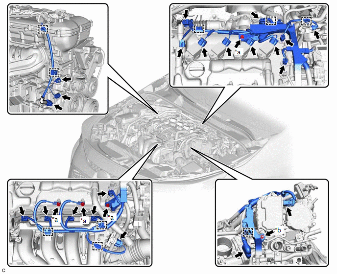
|
*a |
Bolt |
*b |
Nut |
(1) Disengage the 9 clamps, and then disconnect the 21 connectors.
(2) Remove the 4 bolts and nut, and disconnect the engine wire.
(b) w/o Canister Pump Module:
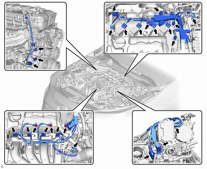
|
*a |
Bolt |
*b |
Nut |
(1) Disengage the 9 clamps, and then disconnect the 20 connectors.
(2) Remove the 4 bolts and nut, and disconnect the engine wire.
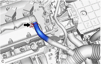
3. DISCONNECT NO. 2 VENTILATION HOSE
|
(a) Slide the clip and disconnect the No. 2 ventilation hose from the cylinder head cover sub-assembly. |
|
4. REMOVE PURGE VALVE (PURGE VSV)
|
(a) Disconnect the No. 1 fuel vapor feed hose from the intake manifold. |
|
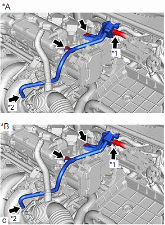
(b) Slide the clip and disconnect the fuel vapor feed hose from the purge valve (purge VSV).
(c) Remove the 2 bolts and purge valve (purge VSV) from the cylinder head cover sub-assembly.
5. REMOVE IGNITION COIL ASSEMBLY
Click here
6. REMOVE CYLINDER HEAD COVER SUB-ASSEMBLY
Click here
7. REMOVE CYLINDER HEAD COVER GASKET
Click here
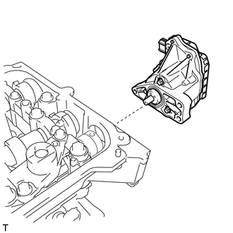
8. REMOVE CONTINUOUSLY VARIABLE VALVE LIFT CONTROLLER ASSEMBLY
|
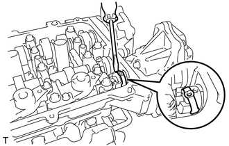
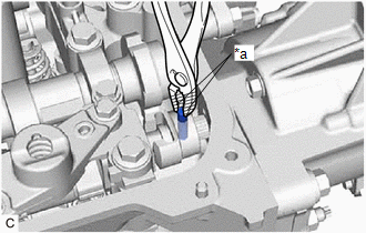
(a) Using a screwdriver, slide the valve lift control actuator connector clip from the valve lift control actuator connector. NOTICE: Slide only the upper part of the valve lift control actuator connector clip, as the straight pin will fall out from the bottom if the valve lift control actuator connector clip is completely removed. |
|
|
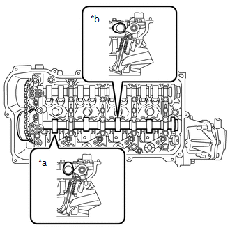
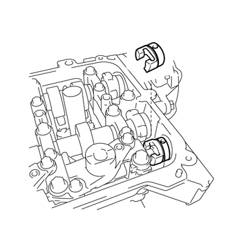
(b) Rotate the crankshaft clockwise until the intake camshaft position at the No. 1 cylinder and No. 3 cylinder are as shown in the illustration. HINT: If the intake camshaft position is not as shown in the illustration, rotate the crankshaft clockwise again so that the intake camshaft is aligned as shown in the illustration. |
|
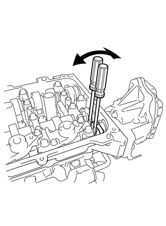
(c) Turn the crankshaft counterclockwise approximately 10 to 15°.
|
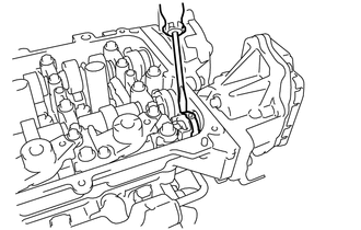
(d) Using 2 screwdrivers, lightly pry the valve lift control actuator connector to make a space between the continuously variable valve lift controller assembly and camshaft housing sub-assembly. NOTICE:
|
|
|
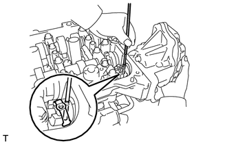
(e) Using a Magnet Hand, remove the straight pin from the valve lift control actuator connector. NOTICE: Do not drop the straight pin into the engine. HINT:
|
|
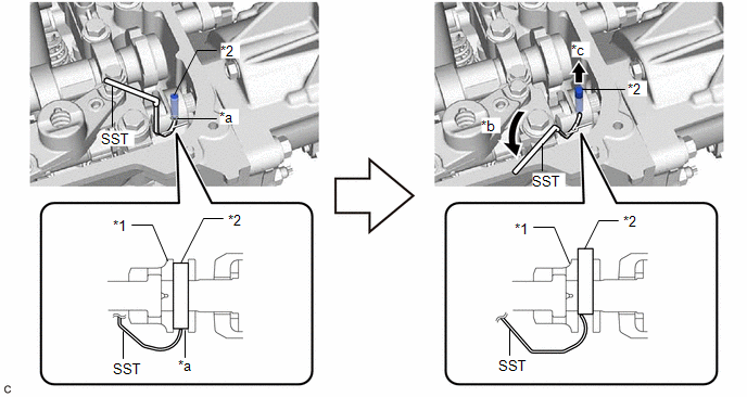
(f) *1 (If straight pin could not be removed)
(1) Using a screwdriver, remove the valve lift control actuator connector clip from the valve lift control actuator connector.
NOTICE:
Do not drop the valve lift control actuator connector clip into the engine.
(2) Align the end of SST with the straight pin hole of the valve lift control actuator connector and push up the straight pin approximately 5 mm (0.197 in.) as shown in the illustration.
|
*1 |
Valve Lift Control Actuator Connector |
*2 |
Straight Pin |
|
*a |
Straight Pin Hole |
*b |
Tilt |
|
*c |
Push up |
- |
- |
SST: 09249-37020
|
(3) Using pliers, remove the straight pin from the valve lift control actuator connector. NOTICE:
|
|
|
(g) *2 (If straight pin could be removed) (1) Using a screwdriver, remove the valve lift control actuator connector clip from the valve lift control actuator connector. NOTICE: Do not drop the valve lift control actuator connector clip into the engine. |
|
|
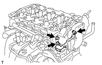
(h) Remove the 2 nuts and wire harness clamp bracket from the camshaft housing sub-assembly. |
|
(i) Remove the bolt from the continuously variable valve lift controller assembly.
|
(j) Remove the continuously variable valve lift controller assembly from the camshaft housing sub-assembly. NOTICE: If the continuously variable valve lift controller assembly has been struck or dropped, replace it. |
|
|
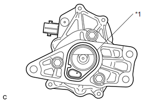
(k) Remove the O-ring from the continuously variable valve lift controller assembly. |
|
|
(l) Remove the valve lift control actuator connector from the valve rocker shaft assembly. |
|
|
|
|