| Last Modified: 05-13-2024 | 6.11:8.1.0 | Doc ID: RM100000001HS28 |
| Model Year Start: 2020 | Model: Corolla Hatchback | Prod Date Range: [03/2019 - 09/2019] |
| Title: M20A-FKS (ENGINE MECHANICAL): ENGINE ASSEMBLY: INSTALLATION; 2020 MY Corolla Corolla Hatchback [03/2019 - 09/2019] | ||
INSTALLATION
CAUTION / NOTICE / HINT
CAUTION:
The engine assembly with transaxle is very heavy. Be sure to follow the procedure described in the repair manual, or the engine lifter may suddenly drop.
NOTICE:
When the manual transaxle assembly is removed, be sure to use a new clutch release cylinder with bearing assembly and new installation bolts. Removal of the manual transaxle assembly allows the compressed clutch release cylinder with bearing assembly to return to its original position. Dust from the moving section may damage the seal of the clutch release cylinder with bearing assembly, possibly causing clutch fluid leaks.
HINT:
Perform "Inspection After Repair" after replacing the engine assembly.
PROCEDURE
1. INSTALL ENGINE HANGER
2. REMOVE ENGINE FROM ENGINE STAND
(a) Remove the engine assembly from the engine stand.
3. INSTALL COMPRESSOR ASSEMBLY WITH PULLEY
4. INSTALL GENERATOR ASSEMBLY
5. INSTALL V-RIBBED BELT
6. INSTALL NO. 1 CRANKSHAFT POSITION SENSOR PLATE
7. INSTALL DRIVE PLATE AND RING GEAR SUB-ASSEMBLY (for CVT)
8. INSTALL FLYWHEEL SUB-ASSEMBLY (for Manual Transaxle)
9. INSTALL CLUTCH DISC ASSEMBLY (for Manual Transaxle)
10. INSTALL CLUTCH COVER ASSEMBLY (for Manual Transaxle)
11. INSPECT AND ADJUST CLUTCH COVER ASSEMBLY (for Manual Transaxle)
12. INSTALL CLUTCH RELEASE CYLINDER WITH BEARING ASSEMBLY TO BLEEDER TUBE (for Manual Transaxle)
13. INSTALL CLUTCH RELEASE CYLINDER WITH BEARING ASSEMBLY (for Manual Transaxle)
14. INSTALL CLUTCH RELEASE BLEEDER SUB-ASSEMBLY (for Manual Transaxle)
15. INSTALL BLEEDER TO FLEXIBLE HOSE TUBE (for Manual Transaxle)
16. INSTALL ENGINE ASSEMBLY (for CVT)
|
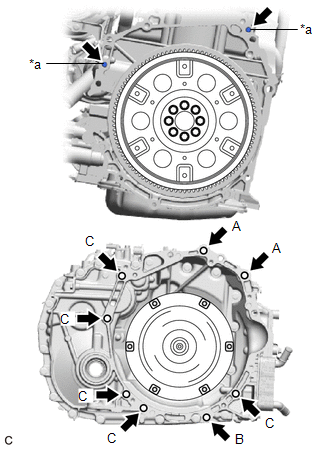
(a) Confirm that the 2 knock pins are installed to the engine assembly and are not damaged. |
|
(b) Install the engine assembly to the continuously variable transaxle assembly with the 8 bolts.
Torque:
Bolt (A) :
64 N·m {653 kgf·cm, 47 ft·lbf}
Bolt (B) :
25 N·m {255 kgf·cm, 18 ft·lbf}
Bolt (C) :
46 N·m {469 kgf·cm, 34 ft·lbf}
Bolt Length:
|
Bolt |
Length |
|---|---|
|
(A) |
50 mm (1.97 in.) |
|
(B) |
35 mm (1.38 in.) |
|
(C) |
45 mm (1.77 in.) |
NOTICE:
- Make sure that the wire harness or similar items are not pinched between the contact surfaces.
- Do not use excess force when installing the continuously variable transaxle assembly.
- When mounting the continuously variable transaxle assembly to the engine assembly, make sure to securely fit the knock pins into the knock holes.
- Check that the torque converter assembly rotates.
- When tightening the bolts, be sure that the mating surfaces of the engine assembly and the continuously variable transaxle assembly are in close contact with one another.
HINT:
- Bolt (A), (B): Install from continuously variable transaxle assembly side.
- Bolt (C): Install from engine assembly side.
17. INSTALL ENGINE ASSEMBLY (for Manual Transaxle)
|
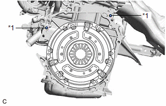
(a) Check that the 2 knock pins are installed on the engine assembly before installing the manual transaxle assembly. |
|
(b) Align the input shaft with the clutch disc and install the engine assembly to the manual transaxle assembly.
|
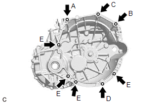
(c) Temporarily install the bolt (A). HINT: Bolt (A): Install from the manual transaxle assembly side. |
|
(d) Install the bolt (B).
Torque:
64 N·m {653 kgf·cm, 47 ft·lbf}
HINT:
Bolt (B): Install from the manual transaxle assembly side.
(e) Install the bolt (C), then fully tighten the bolt (A).
Torque:
Bolt (C) :
64 N·m {653 kgf·cm, 47 ft·lbf}
Bolt (A) :
46 N·m {469 kgf·cm, 34 ft·lbf}
HINT:
Bolt (C): Install from the manual transaxle assembly side.
(f) Install the bolt (D).
Torque:
25 N·m {255 kgf·cm, 18 ft·lbf}
HINT:
Bolt (D): Install from the manual transaxle assembly side.
(g) Install the 4 bolts (E).
Torque:
46 N·m {469 kgf·cm, 34 ft·lbf}
NOTICE:
- Make sure that the wire harness or similar items are not pinched between the contact surfaces.
- Do not forcibly pry on the manual transaxle assembly when installing it to the engine assembly.
- Do not apply excessive force to the manual transaxle assembly as this will break the input shaft.
- Make sure that the knock pins fit securely into the holes when installing the manual transaxle assembly to the engine assembly.
- Make sure that the contact surfaces of the engine assembly and manual transaxle assembly are flat against each other before tightening the bolts.
HINT:
Bolt (E): Install from the engine assembly side.
18. CONNECT WATER BY-PASS HOSE ASSEMBLY (for CVT)
(a) Connect the water by-pass hose assembly to the No. 3 water by-pass pipe sub-assembly and slide the hose clip to secure it.
19. CONNECT WATER INLET HOSE (for CVT)
(a) Connect the water inlet hose to the No. 1 water by-pass hose assembly and slide the hose clip to secure it.
20. INSTALL DRIVE PLATE AND TORQUE CONVERTER ASSEMBLY SETTING BOLT (for CVT)
21. INSTALL FLYWHEEL HOUSING UNDER COVER
(a) Engage the 2 claws and guide to install the flywheel housing under cover to the cylinder block sub-assembly.
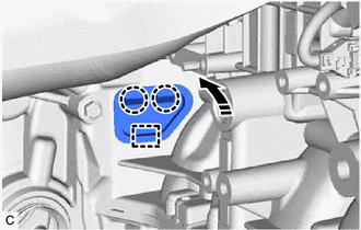

|
Install in this Direction |
22. INSTALL DRIVE SHAFT HEAT INSULATOR SUB-ASSEMBLY
23. INSTALL MANIFOLD STAY
24. INSTALL ENGINE WIRE
(a) Connect all the connectors and clamps, and install the engine wire to the engine assembly with transaxle.
25. INSTALL FLYWHEEL HOUSING SIDE COVER
(a) Install the flywheel housing side cover to the cylinder block sub-assembly.
26. INSTALL STARTER ASSEMBLY
27. INSTALL ENGINE MOUNTING INSULATOR SUB-ASSEMBLY RH
HINT:
Perform this procedure only when replacement of the engine mounting insulator sub-assembly RH is necessary.
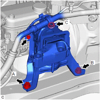
(a) Type A:
|
(1) Temporarily install the engine mounting insulator sub-assembly RH to the vehicle. |
|
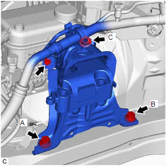
(2) Install the 2 bolts and nut in the order shown in the illustration.
Torque:
72 N·m {734 kgf·cm, 53 ft·lbf}
NOTICE:
Temporarily tighten the bolt (A), and then fully tighten the 2 bolts and nut in the order of (B), (A) and (C).
(3) Connect the air conditioner tube and accessory assembly with the bolt.
Torque:
9.8 N·m {100 kgf·cm, 87 in·lbf}
(4) Install the No. 2 earth wire to the engine mounting insulator sub-assembly RH and vehicle with the 2 bolts.
Torque:
10.5 N·m {107 kgf·cm, 8 ft·lbf}
(b) Type B:
|
(1) Temporarily install the engine mounting insulator sub-assembly RH to the vehicle. |
|
(2) Install the 2 bolts and nut in the order shown in the illustration.
Torque:
72 N·m {734 kgf·cm, 53 ft·lbf}
NOTICE:
Temporarily tighten the bolt (A), and then fully tighten the 2 bolts and nut in the order of (B), (A) and (C).
(3) Connect the air conditioner tube and accessory assembly with the bolt.
Torque:
9.8 N·m {100 kgf·cm, 87 in·lbf}
(4) Install the No. 2 earth wire to the engine mounting insulator sub-assembly RH and vehicle with the 2 bolts.
Torque:
10.5 N·m {107 kgf·cm, 8 ft·lbf}
28. INSTALL ENGINE MOUNTING INSULATOR LH
HINT:
Perform this procedure only when replacement of the engine mounting insulator LH is necessary.
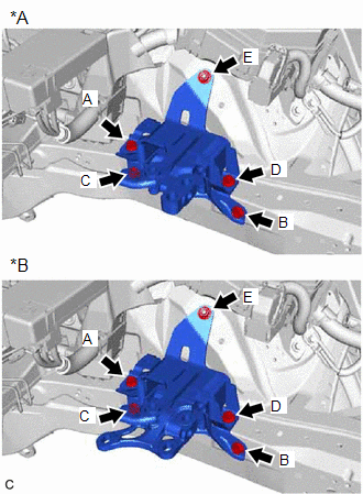
|
(a) Temporarily install the engine mounting insulator LH to the vehicle. |
|
(b) Install the 4 bolts and nut in the order shown in the illustration.
Torque:
42 N·m {428 kgf·cm, 31 ft·lbf}
NOTICE:
Temporarily tighten the bolt (A), and then fully tighten the 4 bolts and nut in the order of (B), (C), (D), (A) and (E).
29. REMOVE ENGINE HANGER
30. INSTALL FUEL DELIVERY GUARD
(a) Install the fuel delivery guard to the engine mounting bracket RH with the bolt.
Torque:
40 N·m {408 kgf·cm, 30 ft·lbf}
31. INSTALL ENGINE ASSEMBLY WITH TRANSAXLE
(a) Using height adjustment attachments and plate lift attachments to keep the engine assembly with transaxle and front suspension crossmember sub-assembly level, set an engine lifter underneath the engine assembly with transaxle and front suspension crossmember sub-assembly.
NOTICE:
- Using height adjustment attachments and plate lift attachments, keep the engine assembly with transaxle horizontal.
- Do not perform any procedures while the engine assembly is suspended because doing so may cause the engine assembly to drop, resulting in injury. However, the engine assembly needs to be suspended when it is installed to or removed from an engine stand.
- To prevent the oil pan sub-assembly from deforming, do not place any attachments under the oil pan sub-assembly of the engine assembly with transaxle.
(b) Operate the engine lifter and install the engine assembly with transaxle to the vehicle.
CAUTION:
Do not raise the engine assembly with transaxle more than necessary. If the engine is raised excessively, the vehicle may also be lifted up.
NOTICE:
- Make sure that the engine assembly with transaxle is clear of all wiring and hoses.
- While raising the engine assembly with transaxle into the vehicle, do not allow it to contact the vehicle.
(c) Connect the front suspension crossmember sub-assembly to the vehicle with the 4 bolts.
Torque:
141 N·m {1438 kgf·cm, 104 ft·lbf}
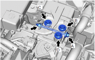
(d) for CVT:
|
(1) Install the engine mounting insulator LH to the engine mounting bracket LH with the 3 bolts, through bolt and nut in the order shown in the illustration. Torque: 44 N·m {449 kgf·cm, 32 ft·lbf} NOTICE:
|
|
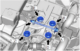
(e) for Manual Transaxle:
|
(1) Install the engine mounting insulator LH to the engine mounting bracket LH with the 4 bolts, through bolt and nut in the order shown in the illustration. Torque: 44 N·m {449 kgf·cm, 32 ft·lbf} NOTICE:
|
|
(f) Install the engine mounting insulator sub-assembly RH to the engine mounting bracket RH with the 2 bolts and nut.
Torque:
Bolt :
72 N·m {734 kgf·cm, 53 ft·lbf}
Nut :
41 N·m {418 kgf·cm, 30 ft·lbf}
32. INSTALL REAR SIDE RAIL REINFORCEMENT SUB-ASSEMBLY LH
33. INSTALL REAR SIDE RAIL REINFORCEMENT SUB-ASSEMBLY RH
HINT:
Use the same procedure as for the LH side.
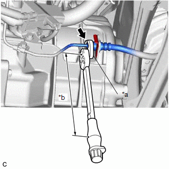
34. CONNECT NO. 1 CLUTCH HOSE (for Manual Transaxle)
(a) Connect the No. 1 clutch hose to the clutch flexible hose bracket with a new clip.
|
(b) Using a 10 mm union nut wrench, connect the bleeder to flexible hose tube to the No. 1 clutch hose. Torque: Specified tightening torque : 15.2 N·m {155 kgf·cm, 11 ft·lbf} |
|
35. INSTALL DRIVE SHAFT ASSEMBLY
36. INSTALL FRONT EXHAUST PIPE ASSEMBLY (TWC: Rear Catalyst)
37. INSTALL FRONT FLOOR CENTER BRACE
38. INSTALL FRONT FLOOR COVER LH
39. INSTALL FRONT FLOOR COVER RH
40. CONNECT NO. 1 STEERING COLUMN HOLE COVER SUB-ASSEMBLY
41. CONNECT NO. 2 STEERING INTERMEDIATE SHAFT ASSEMBLY
42. INSTALL COLUMN HOLE COVER SILENCER SHEET
43. CONNECT SUCTION HOSE SUB-ASSEMBLY
44. CONNECT DISCHARGE HOSE SUB-ASSEMBLY
45. CONNECT NO. 2 WATER BY-PASS HOSE
(a) Connect the No. 2 water by-pass hose to the No. 2 water by-pass pipe assembly and slide the hose clip to secure it.
46. CONNECT FUEL TUBE SUB-ASSEMBLY
(a) Connect the fuel tube sub-assembly to the fuel pump assembly.
(b) Engage the clamp to connect the fuel tube sub-assembly.
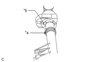
47. CONNECT OUTLET HEATER WATER HOSE
|
(a) Align the protrusion of the No. 2 water by-pass pipe sub-assembly with the cutout in the outlet heater water hose connector and push them together until the outlet heater water hose makes a "click" sound. |
|
(b) Push in the retainer.
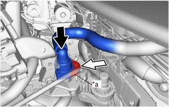
|
*a |
Retainer |

|
Push |

|
Push in |
(c) Check that the No. 2 water by-pass pipe sub-assembly and outlet heater water hose connector are securely connected by pulling on them.
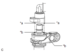
48. CONNECT INLET HEATER WATER HOSE
|
(a) Align the protrusions of the inlet heater water hose connector with the cutouts in the flow shutting valve (water valve) and push them together until the inlet heater water hose connector makes a "click" sound. |
|
(b) Push in the retainer.
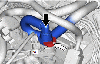
|
*a |
Retainer |

|
Push |

|
Push in |
(c) Check that the flow shutting valve (water valve) and inlet heater water hose connector are securely connected by pulling on them.
49. CONNECT NO. 1 FUEL VAPOR FEED HOSE
(a) Connect the No. 1 fuel vapor feed hose to the vacuum surge tank and slide the hose clip to secure it.
(b) Engage the clamp to connect the No. 1 fuel vapor feed hose.
50. CONNECT NO. 1 VACUUM HOSE CONNECTOR
51. CONNECT NO. 2 RADIATOR HOSE
(a) Connect the No. 2 radiator hose to the radiator assembly and slide the clip to secure it.
(b) Engage the clamp to connect the No. 2 radiator hose.
52. CONNECT NO. 1 RADIATOR HOSE
(a) Connect the No. 1 radiator hose to the water outlet and slide the clip to secure it.
53. CONNECT FLOOR SHIFT TRANSMISSION CONTROL SELECT CABLE (for CVT)
NOTICE:
Before connecting the floor shift transmission control select cable, check that the shift lever is in N.
(a) Turn the transmission control shaft lever clockwise until it stops, then turn it counterclockwise 2 notches.
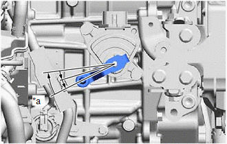
|
*a |
N |
NOTICE:
If the transmission control shaft lever is turned counterclockwise more than necessary, manual valve link lever sub-assembly may separate from the manual valve.
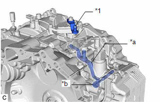
|
*1 |
Transmission Control Shaft Lever |
|
*a |
Manual Valve Link Lever Sub-assembly |
|
*b |
Manual Valve |
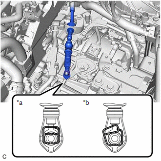
(b) Connect the floor shift transmission control select cable to the No. 1 transmission control cable bracket with a new clip.
|
(c) Connect the floor shift transmission control select cable to the transmission control shaft lever as shown in the illustration. |
|
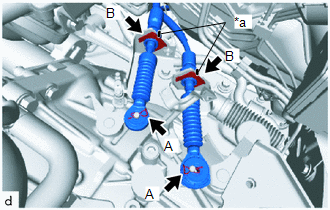
54. CONNECT TRANSMISSION CONTROL CABLE ASSEMBLY (for Manual Transaxle)
|
(a) Install the transmission control cable assembly to the control cable bracket assembly with 2 new clips (B). NOTICE: Make sure that the paint marks on the transmission control cable assembly are aligned with the slits in the control cable bracket assembly before installing the clips. |
|
(b) Connect the transmission control cable assembly to the manual transaxle assembly with the 2 clips (A).
55. INSTALL BATTERY CLAMP SUB-ASSEMBLY
(a) Install the battery clamp sub-assembly to the vehicle with the 3 bolts.
Torque:
15.4 N·m {157 kgf·cm, 11 ft·lbf}
(b) Engage the clamp to connect the engine wire to the battery clamp sub-assembly.
56. CONNECT ENGINE WIRE
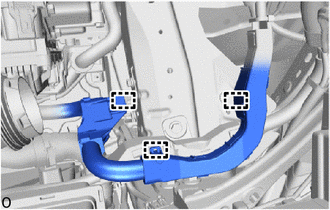
|
(a) Engage the 3 clamps to connect the engine wire to the vehicle. |
|
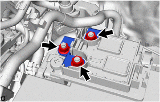
|
(b) Connect the engine wire to the positive (+) battery terminal with the 3 nuts. Torque: 7.6 N·m {77 kgf·cm, 67 in·lbf} |
|
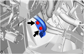
|
(c) Connect the engine wire to the vehicle with the 2 bolts. Torque: 10 N·m {102 kgf·cm, 7 ft·lbf} |
|
57. INSTALL ECM
58. INSTALL BATTERY
59. CONNECT CABLE TO NEGATIVE BATTERY TERMINAL
60. BLEED CLUTCH LINE (for Manual Transaxle)
61. ADD ENGINE OIL
62. ADD ENGINE COOLANT
63. ADD MANUAL TRANSAXLE OIL (for Manual Transaxle)
64. ADD CONTINUOUSLY VARIABLE TRANSAXLE FLUID (for CVT)
65. CHARGE AIR CONDITIONING SYSTEM WITH REFRIGERANT
66. WARM UP ENGINE
67. INSPECT TRANSAXLE OIL (for Manual Transaxle)
68. ADJUST TRANSMISSION CONTROL CABLE ASSEMBLY (for Manual Transaxle)
69. INSPECT SHIFT LEVER POSITION (for CVT)
70. ADJUST SHIFT LEVER POSITION (for CVT)
71. INSPECT FOR ENGINE OIL LEAK
72. INSPECT FOR COOLANT LEAK
73. INSPECT FOR CONTINUOUSLY VARIABLE TRANSAXLE FLUID LEAK (for CVT)
74. INSPECT FOR MANUAL TRANSAXLE OIL LEAK (for Manual Transaxle)
75. INSPECT FOR REFRIGERANT LEAK
76. INSPECT FOR FUEL LEAK
77. INSPECT FOR EXHAUST GAS LEAK
78. CHECK ENGINE OIL LEVEL
79. INSPECT RADIATOR RESERVE TANK ENGINE COOLANT LEVEL
80. INSTALL REAR ENGINE UNDER COVER LH
(a) Type A:
(1) Install the rear engine under cover LH to the vehicle with the 4 clips.
(2) Install the screw.
(b) Type B:
(1) Install the rear engine under cover LH to the vehicle with the 5 clips.
(2) Install the screw.
81. INSTALL REAR ENGINE UNDER COVER RH
(a) Type A:
(1) Install the rear engine under cover RH to the vehicle with the 4 clips.
(2) Install the screw.
(b) Type B:
(1) Install the rear engine under cover RH to the vehicle with the 5 clips.
(2) Install the screw.
82. INSTALL NO. 1 ENGINE UNDER COVER ASSEMBLY
(a) Install the No. 1 engine under cover assembly to the vehicle with the 4 bolts and 10 clips.
Torque:
7.5 N·m {76 kgf·cm, 66 in·lbf}
83. INSTALL FRONT WHEELS
84. INSPECT AND ADJUST FRONT WHEEL ALIGNMENT
85. PERFORM INITIALIZATION
86. INSPECT IGNITION TIMING
87. INSPECT ENGINE IDLE SPEED
88. INSPECT CO/HC
89. CHECK SPEED SENSOR SIGNAL
|
|
|
![2019 - 2020 MY Corolla Corolla Hatchback [06/2018 - 09/2019]; M20A-FKS (ENGINE CONTROL): SFI SYSTEM: INITIALIZATION](/t3Portal/stylegraphics/info.gif)
