| Last Modified: 05-13-2024 | 6.11:8.1.0 | Doc ID: RM100000001HCJR |
| Model Year Start: 2020 | Model: Corolla | Prod Date Range: [01/2019 - 04/2020] |
| Title: HEATING / AIR CONDITIONING: AIR CONDITIONING SYSTEM (for HV Model): B14A2; Driver Side Solar Sensor Short Circuit; 2020 MY Corolla Corolla HV [01/2019 - 04/2020] | ||
|
DTC |
B14A2 |
Driver Side Solar Sensor Short Circuit |
DESCRIPTION
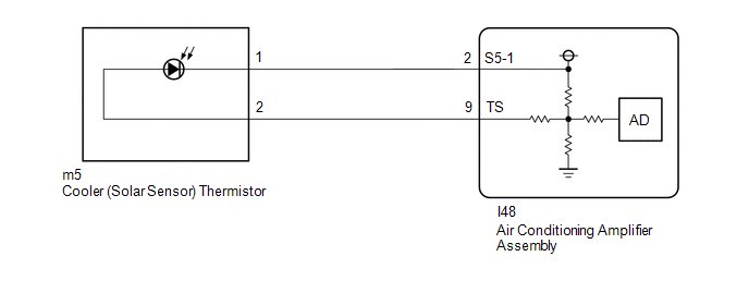
The cooler (solar sensor) thermistor is installed on the upper side of the instrument panel. It detects sunlight to control air conditioning control in AUTO mode. The output voltage from the cooler (solar sensor) thermistor varies in accordance with the amount of sunlight. When the sunlight increases, the output voltage increases. As the sunlight decreases, the output voltage decreases. The air conditioning amplifier assembly detects changes in the output voltage from the cooler (solar sensor) thermistor.
|
DTC No. |
Detection Item |
DTC Detection Condition |
Trouble Area |
Memory |
|---|---|---|---|---|
|
B14A2 |
Driver Side Solar Sensor Short Circuit |
Short in cooler (solar sensor) thermistor circuit |
|
Memorized (4 sec. or more)* |
- *: The air conditioning amplifier assembly stores this DTC if the malfunction has occurred for the period of time indicated in the brackets.
WIRING DIAGRAM
PROCEDURE
|
1. |
READ VALUE USING TECHSTREAM |
(a) Connect the Techstream to the DLC3.
(b) Turn the power switch on (IG).
(c) Turn the Techstream on.
(d) Enter the following menus: Body Electrical / Air Conditioner / Data List.
(e) Read the Data List according to the display on the Techstream.
Body Electrical > Air Conditioner > Data List
|
Tester Display |
Measurement Item |
Range |
Normal Condition |
Diagnostic Note |
|---|---|---|---|---|
|
Solar Sensor (D Side) |
Cooler (solar sensor) thermistor |
Min.: 0 Max.: 255 |
Cooler (solar sensor) thermistor value increase as brightness increases |
Cooler (solar sensor) thermistor circuit malfunction
|
Body Electrical > Air Conditioner > Data List
|
Tester Display |
|---|
|
Solar Sensor (D Side) |
OK:
The display is as specified in the normal condition column.
| OK |

|
|

|
2. |
CHECK HARNESS AND CONNECTOR (POWER SOURCE CIRCUIT) |
(a) Disconnect the m5 cooler (solar sensor) thermistor connector.
(b) Measure the voltage according to the value(s) in the table below.
Standard Voltage:
|
Tester Connection |
Condition |
Specified Condition |
|---|---|---|
|
m5-1 - m5-2 |
Power switch off |
Below 1 V |
|
m5-1 - m5-2 |
Power switch on (IG) |
4.5 to 5.5 V |
| NG |
|
|
|
3. |
INSPECT COOLER (SOLAR SENSOR) THERMISTOR |
(a) Remove the cooler (solar sensor) thermistor.
Click here
![2020 - 2025 MY Corolla Corolla Hatchback Corolla HV GR Corolla [01/2019 - ]; HEATING / AIR CONDITIONING: SOLAR SENSOR: REMOVAL](/t3Portal/stylegraphics/info.gif)
(b) Inspect the cooler (solar sensor) thermistor.
Click here
| OK |
|
| NG |
|
|
4. |
CHECK HARNESS AND CONNECTOR (COOLER (SOLAR SENSOR) THERMISTOR - AIR CONDITIONING AMPLIFIER ASSEMBLY) |
(a) Disconnect the I48 air conditioning amplifier assembly connector.
(b) Measure the resistance according to the value(s) in the table below.
Standard Resistance:
|
Tester Connection |
Condition |
Specified Condition |
|---|---|---|
|
m5-1 - I48-2 (S5-1) |
Always |
Below 1 Ω |
|
m5-2 - I48-9 (TS) |
Always |
Below 1 Ω |
|
m5-1 or I48-2 (S5-1) - Other terminals and body ground |
Always |
10 kΩ or higher |
|
m5-2 or I48-9 (TS) - Other terminals and body ground |
Always |
10 kΩ or higher |
| OK |
|
| NG |
|
REPAIR OR REPLACE HARNESS OR CONNECTOR |
|
|
|